


5
IFN21950
www.chpower.com
OPERATING INSTRUCTIONS
(Continued)
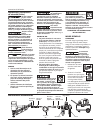
1. The air compressor
must be able to
maintain a minimum
of 70 psi when the
tool is being used. An inadequate air
supply can cause a loss of power and
inconsistent driving.
2. An oiler can be
used to provide oil
circulation through
the tool. A filter can
be used to remove liquid and solid
impurities which can rust or “gum
up” internal parts of the tool.
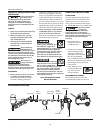
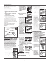
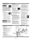
3. Always use air supply hoses with
a minimum working pressure
rating equal to or greater than the
pressure from the power source if a
regulator fails, or 150 psi, whichever
is greater. Use 3/8 inch air hose for
runs up to 50 feet. Use 1/2 inch air
hoses for 50 foot run or longer. For
better performance, install a 3/8 inch
quick plug (1/4 inch NPT threads)
with an inside diameter of .315 inch
(8mm) on the tool and a 3/8 inch
quick coupler on the air hose.
4. Use a pressure regulator on the
compressor, with an operating
pressure of 0 - 125 psi. A pressure
regulator is required to control
the operating pressure of the tool
between 70 and 120 psi.
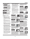
NO-MAR DECKING TIP
The no-mar decking tip is designed to
eliminate marks caused by the serrated
work contact element (WCE). The no-
mar tip may be removed if not required
(See REMOVING NO-MAR DECKING
TIP). Use tool in single cycle mode (SEE
OPERATIONAL MODES) when no-mar
tip is in place.
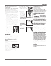
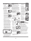
REMOVING NO-MAR DECKING TIP
1. Disconnect air supply
from nailer.
2. Remove all fasteners from magazine
(See UNLOADING THE NAILER).
3. Remove no-mar tip retaining ring.
4. Pry no-mar tip
away from the
work contact
element.
5. Replace retaining
ring onto no-mar
tip, then store tip
in safe place for
future use.
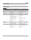
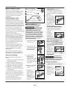
INSTALLING NO-MAR DECKING TIP
1. Disconnect air supply
from nailer.
2. Remove all fasteners from magazine
(See UNLOADING THE NAILER).
3. Remove retaining
ring from no-mar tip.
4. Carefully place no-
mar tip over the
end of work contact
element. Position tip
onto WCE making
certain serrated
gooves on each piece
are in line and fit
snugly together.
5. Position retaining
ring on no-mar tip
and press firmly in
place.
6. Check that the WCE
and trigger move
up and down freely
without sticking or
binding.
OPERATIONAL MODE
Always know the
operational mode of
the tool before using. Failure to know
the operational mode could result in
death or serious personal injury.
SINGLE CYCLE MODE
When the black trigger is installed,
nailer is in single cycle mode. This
method is recommended when precise
nail placement is required. Operation in
this mode requires trigger to be pulled
each time a nail is driven.
Nailer can be actuated by depressing
the Work Contact Element (WCE)
against work surface followed by
pulling the trigger.
The trigger must be released after each
fastener is driven to allow tool to reset.
Since the tool can only be actuated
by first removing the finger from the
trigger, this is considered to be a more
restrictive mode of operation, suitable
for less experienced users.
BOTTOM TRIP MODE
When the red trigger is installed, the
nailer is in bottom trip mode. This
method is recommended when less
precise nail placement is required.
Operation in this mode requires trigger
to be depressed with nailer off of
the work surface. Then, the nose of
the nailer is tapped against the work
surface causing a nail to be driven.
Each time the Work Contact Element is
depressed, a nail is driven into the work
surface. Extreme care should be taken
because a nail will be driven when the
WCE is pressed against any surface.
Since the tool can be actuated without
removing the finger from the trigger,
this is considered to be a less restrictive
mode, suitable for more experienced
users.
70 psi
Min.
120 psi
Max.
150 psi or greater
3/8 inch I.D.
Retaining
Ring
No-Mar Tip
Work
Contact
Element
No-
Mar
Tip
Grooves