5
WG3013
if the duty cycle is exceeded. Welding
operations may continue when the
yellow lamp is no longer illuminated.
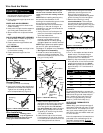
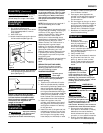
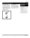
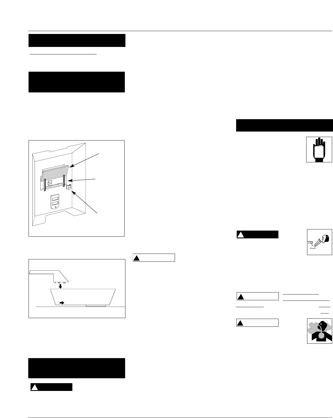
1. Cut retainer stiffeners and
detachable handle away from shield.
Trim the excess plastic to remove
sharp edges.
2. Insert filter lens.
3. Attach the stiffeners over the pins on
the lens retainers (See Figure 6).
4. To attach the handle, place shield on
a flat surface and press handle into
place (See Figure 7).
NOTE: If you have never welded
before or have little experience, a
full face helmet is recommended.
Both hands are needed to stabilize
and control the angle and arc
length of the torch.
Improper handling
and maintenance
of compressed gas cylinders and
regulators can result in serious injury
!
DANGER
or death! Always secure gas cylinders
to the tank bracket kit, a wall or other
fixed support to prevent the cylinder
from falling over. Read, understand,
and follow all the compressed gases
and equipment hazards in the safety
instructions.
NOTE: Shielding gas is not required if
flux-cored welding wire is used.
GAS TYPES
There are 3 types of gas generally used
for gas metal arc welding; 100% argon,
a mixture of 75% argon and 25%
carbon dioxide (C25) or 100% carbon
dioxide. However, 100% carbon
dioxide is not recommended due to
unsatisfactory weld beads. This welder
does not perform well with 100%
carbon dioxide. The 75/25 mixture is
recommended for general steel
welding. For aluminum welding, use
100% argon. Cylinders of either type
gas may be obtained at your local
welding supply outlet. Secure cylinder
in place on your welding machine or
other support to prevent the cylinder
from falling over.
NOTE: Use of incorrect gas may lead to
little or no penetration of welding
bead.
REGULATOR (NOT INCLUDED)
The regulator provides a constant
shielding gas pressure and flow rate
during the welding process.
HOOKUP PROCEDURE
Cylinder gas is
under high
pressure. Point cylinder outlet away
from yourself and any bystanders
before opening.
1. These units fit a 20 cubic ft bottle.
2. With the cylinder securely installed,
remove the cylinder cap, stand to the
side of the cylinder opposite the
outlet, and open the valve slightly,
turning counterclockwise. When gas
is emitted from the cylinder, close the
valve by turning clockwise. This will
blow out dust or dirt that may have
accumulated around the valve seat.
3. Install the regulator onto the
cylinder valve, keeping the face of
the gauges in the vertical position
and tighten the stem nut securely
to the gas valve.
4. Install one end of the gas hose (not
included) to the fitting on the rear
of the welder and the other end to
the fitting on the regulator using
hose clamps (not included) on each
!
WARNING
connection. Make sure the gas hose
is not kinked or twisted.
5. Once again, stand opposite the
cylinder outlet and slowly open the
cylinder valve. Inspect for leaks in
the connections.
6. Pull the trigger on the gun to allow
the gas to flow. While the trigger is
pulled and gas is flowing, adjust the
gas regulator to 30-35 cfh (cubic
feet per hour). Release the trigger.
7. Remember to close the gas valve
when finished welding.
1. Be sure to read,
understand, and comply
with all precautions in
the General Safety
Information section. Be
sure to read the entire section
entitled Welding Guidelines prior to
using this equipment.
2. Verify welder is off.
3. Verify that the surfaces of metals to
be joined are free from dirt, rust,
paint, oil, scale or other contam-
inants. These contaminants make
welding difficult and cause poor
welds.
All persons operating this
equipment or in the area
while equipment is in use
must wear protective welding gear
including: eye protection with proper
shade, flame resistant clothing, leather
welding gloves, and full foot
protection.
WHETHER OR
NOT THE TRIGGER
IS PULLED, the welding wire is LIVE
whenever the welder is turned ON.
If heating, welding, or
cutting materials that are
galvanized, zinc plated, lead,
or cadmium plated refer to the General
Safety Information Section for
instructions. Extremely toxic fumes are
created when these metals are heated.
4. Connect the work clamp to the
work piece or workbench (if metal).
Make sure the contact is secure.
Avoid surfaces with paint, varnish,
corrosion, or non-metallic materials.
5. Position the Heat Selector on the
front panel to the desired setting.
!
WARNING
!
CAUTION
!
DANGER
Assembly
(Continued)
Shielding Gas
Installation
Handshield
Assembly
Figure 6
Lens
Lens
Retainer
Retainer
Stiffener
Figure 7
www.chpower.com
Operation
MANUAL


