


WL6000 Series
3
Operating Instructions
NOTE: 120 volt, 15 amp units can be
operated on a 120 volt circuit under
the following conditions:
a. No other electrical appliances
or lights are connected to the same
branch circuit.
b.Voltage supply is normal.
c. Circuit is equipped with a 15
amp circuit breaker or a 15
amp slow blow fuse.
3. If these conditions cannot be met or
if nuisance tripping of current
protection device occurs, it may be
necessary to operate compressor
from a 120 volt, 20 amp circuit.
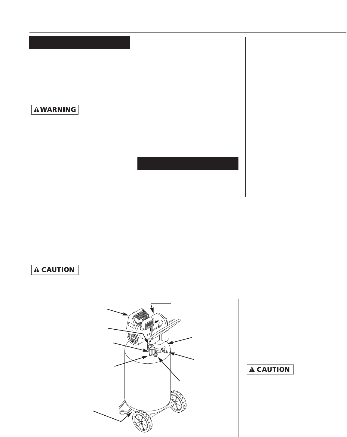
Pressure switch - Auto/Off Switch - In
the AUTO position, the compressor
shuts off automatically when tank
pressure reaches the maximum preset
pressure. In the OFF position, the
compressor will not operate. This
switch should be in the OFF position
when connecting or disconnecting the
power cord from the electrical outlet or
when changing air tools.
Regulator - The regulator controls the
amount of air pressure released at the
hose outlet.
ASME Safety Valve - This valve
automatically releases air if the tank
pressure exceeds the preset maximum.
Discharge tube - This tube carries
compressed air from the pump to the
check valve. This tube becomes very hot
during use. To avoid the risk of severe
burns, never touch the discharge tube.
Check valve - One-way valve that
allows air to enter the tank, but
prevents air in the tank from flowing
back into the compressor pump.
Drain Petcock - This valve is located on
the bottom of the tank. Use this valve
to drain moisture from the tank daily
to reduce the risk of corrosion.
Reduce tank pressure below 10 PSI,
then drain moisture from tank daily to
avoid tank corrosion. Drain moisture
from tank(s) by opening the drain
petcock located underneath the tank.
LUBRICATION
This is an oilless product and does not
require lubrication to operate.
BREAK-IN PROCEDURE
Do not attach air
chuck or other tool
to open end of hose until start-up has
been completed and unit checks OK.
IMPORTANT: Do not operate
compressor before reading instructions
or damage may result.
1. Turn regulator fully clockwise to
open air flow.
2. If repair or replacement of cord or
plug is necessary, do not connect
grounding wire to either flat blade
terminal. The wire with insulation
having an external surface that is
green (with or without yellow
stripes) is the grounding wire.
Never connect
green (or green
and yellow) wire to a live terminal.
3. Check with a qualified electrician or
serviceman if grounding instructions
are not completely understood, or if
in doubt as to whether product is
properly grounded. Do not modify
plug provided; if it will not fit outlet,
have proper outlet installed by a
qualified electrician.
WIRING
1. Local electrical wiring codes differ
from area to area. Source wiring,
plug and protector must be rated for
at least the amperage and voltage
indicated on motor nameplate, and
meet all electrical codes for this
minimum.
2. Use a slow blow fuse or a circuit
breaker.
Overheating, short
circuiting and fire
damage will result from inadequate
wiring, etc.
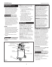
Operation
Figure 2
Drain
Petcock
Safety
Valve
Pressure
Switch
Regulator
Check Valve
(Opposite Side)
Air Hose
Attachment
Discharge Tube
(Opposite Side)
Tank Pressure Gauge
Outlet Pressure Gauge
Installation (Con’t)
MOISTURE IN COMPRESSED AIR
Moisture in compressed air will
form into droplets as it comes from
an air compressor pump. When
humidity is high or when a
compressor is in continuous use for
an extended period of time, this
moisture will collect in the tank.
When using a paint spray or
sandblast gun, this water will be
carried from the tank through the
hose, and out of the gun as droplets
mixed with the spray material.
IMPORTANT: This condensation
will cause water spots in a paint
job, especially when spraying other
than water based paints. If
sandblasting, it will cause the sand
to cake and clog the gun,
rendering it ineffective. A filter in
the air line (MP3105), located as
near to the gun as possible, will
help eliminate this moisture.