


6
Air Filter(s) — Air filter(s) should be checked monthly
and changed when necessary. Units may have either 2-in. or
4-in. thick filters. For units with 2-in. thick filters, all filters will
be 20 x 24 x 2-in. size. For units with 4-in. thick filters, half the
filters will be 20 x 24 x 4-in. size and half will be 20 x 20 x
4-in. size. The filter access panel is located at the end of the unit
opposite of the condenser section. The access door is labeled to
indicate that it is the filter access door.
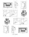
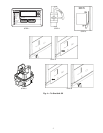
To replace or inspect filters:
1. Loosen the 3 latches securing the filter access door and
open door.
2. Remove the bolt securing the inner access panel, located
behind the filter access door, using care not to lose the
bolt.
3. Remove the inner access panel.
4. Slide the black plastic filter retainer towards you and
remove.
5. Remove filters by pulling toward you and away from the
filter track.
6. A filter removal rod is shipped taped to the partition
located near the bottom filter track. The filter removal rod
will aid in the removal of filters beyond the reach of the
service person.
7. Inspect or replace filters.
8. Return filters to filter tracks. Note direction of airflow
arrows on filter frame.
9. Reinstall the black plastic filter retainer.
10. Place the filter removal rod back on the partition for
future use.
11. Reinstall inner panel.
12. Reinstall bolt securing the inner panel.
13. Close filter access panel and tighten latches.
If you have difficulty in locating your air filter or if you
have questions concerning proper filter maintenance, contact
your dealer for instructions. When replacing your unit filters,
always use the same size and type of filter that was originally
supplied by the installer.
Units with outdoor air capability have a cleanable filter for
the outdoor air. This filter should be checked annually and
cleaned as necessary with steam or hot water and a mild deter-
gent. Do not use throwaway filters in place of cleanable filters.
Heat Exchanger — To ensure dependable and efficient
heating operation, the heat exchanger should be checked by a
qualified maintenance person before each heating season and
cleaned when necessary. This checkout should not be attempt-
ed by anyone not having the required expertise and equipment
to do the job properly. Checking and/or cleaning the heat
exchanger involves removing the gas controls assembly, the
flue collector box, and the flue collector box cover. When
finished, the gas controls assembly must be reinstalled for
proper operation. Also, the flue collector box cover must be
replaced correctly so that a proper seal is maintained. Refer to
unit installation instructions for correct procedure. Contact
your dealer for the required periodic maintenance.
Fans and Belts — Periodically check the condition of
the fan wheels and housings, and belt tension. When service is
necessary, call your dealer.
Indoor-Fan Motor, Outdoor-Fan Motor, and
Combustion Fan Motor —
Lubrication is not recom-
mended. Bearings will not require lubrication for at least
5 years of normal operation. After 5 years, motor life can be
extended by having the motors serviced at an authorized motor
service shop.
Fan Shaft Bearings — The bearings should be greased
with Shell Alvania no. 2 grease or equivalent. The bearings
will need to be greased annually, dependent on fan usage. Do
not grease more than once a year.
Evaporator and Condenser Coils — Cleaning of
the coils should be done by qualified service personnel.
Contact your dealer for the required annual maintenance.
Condensate Drain — The drain pan and condensate
drain line should be checked and cleaned at the same time the
cooling coils are checked by your dealer.
Compressor — All compressors are factory supplied with
a normal charge of the correct type of refrigeration-grade oil in
them and should not require additional oil.
Condenser Fan
The fan must be kept free of all obstructions to ensure prop-
er cooling. Contact your dealer for any required service.
Electrical Controls and Wiring — Electrical con-
trols are difficult to check without proper instrumentation. If
there are any discrepancies in the operating cycle, contact your
dealer and request service.
Refrigerant Circuit — The refrigerant circuit is difficult
to check for leaks without the proper equipment. If inadequate
cooling is suspected, contact your local dealer for service.
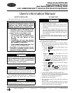
Combustion Area and Vent System — The com-
bustion area and vent system should be visually inspected be-
fore each heating season. The normal accumulation of dirt,
soot, rust, and scale can result in loss of efficiency and im-
proper performance if allowed to build up.
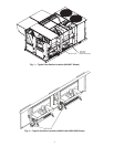
See Fig. 1 and 2 and proceed as follows to inspect the com-
bustion area and power-venting system of your unit.
1. Turn off gas supply to your unit.
2. Turn off electrical power to your unit.
3. Remove gas section access panels.
4. Using a flashlight, carefully inspect the burner areas for
dirt, soot, rust, or scale.
5. When you have completed your inspection, follow the To
Light Unit section in this manual to restore your unit to
operation.
WARNING
Never operate your unit without filters in place. Failure to
heed this warning may result in damage to the blower
motor and/or compressor. An accumulation of dust and lint
on internal parts of your unit can cause loss of efficiency
and, in some cases, fire.
WARNING
Do not poke sticks, screwdrivers, or any other object into
revolving fan blades. Severe bodily injury may result.
CAUTION
If your unit makes any unusual or especially loud noises
during heating, shut down the heating section and call your
dealer.
CAUTION
If dirt, soot, rust, or scale accumulations are found, call
your dealer and do not operate your heating section.