


5.02.1 Connect a 100 watt light bulb to the
inverter output.
5.02.2 Make sure the inverter is turned
"On", the output circuit breaker is reset and that
the voltage is at least 12VDC, 24VDC or 48 VDC
(depending on inverter model) at the DC input
terminals. If not, check DC wiring connections
and the line fuse.
5.02.3 Check the connection to the
remote switch, +12VDC, +24VDC or +48VDC
must be present at the violet wire for the unit to
operate. If not, check any in-line fuses in the
+12VDC, +24 or +48 VDC remote switch circuit.
5.02.4 Observe the fault indicating lights
on the front of the inverter.
a) The Low battery light indicates a low
battery condition. Switch the inverter “Off” for 5
seconds, then “On” again. The light coming on
again indicates a fault in the battery wiring, battery
capacity and voltage or the fuse.
b) The Overload light indicates an output
wiring short circuit or a load that is too large for the
power rating of the inverter. Switch the inverter
“Off”, remove the short circuit or excessive load
from the output, then switch the inverter back
“On”.
c) The High temp. light indicates the inverter
has overheated. The unit will automatically turn
back on when it has cooled to 40
0
C (104
0
F).
5.03 If the above steps are completed and the
inverter still will not operate satisfactorily call Airpax
Dimensions, Inc. for a return authorization number.
Page 4
voltage, Class 2, wiring code. The On/Off switch
and in-line fuse to be purchased locally at an
electrical supply outlet.
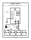
3.06.2 A 3 Amp rated remote switch must
be connected to the violet wire marked “Remote
On/Off” coming out at front of the inverter.
Connect the violet wire to the load side of the
remote switch. The line side of the switch must be
connected to the DC power source with a 3 Amp
fuse within 18" of the source. The cable clamp
strain relief should be used to secure the field wires.
3.06.3 The switch should be mounted at a
convenient location in a listed outlet box with
approved strain relief. The in-line fuse to be
mounted on appropriate fuse holder.
3.06.4
NOTE:
A remote switch, must be
installed to operate the inverter. You may use
several switches or relays in parallel in lieu of one
remote switch.
3.07 120 VAC Output
3.07.1
CAUTION:
Do not connect another
source of AC power directly to the output of the
inverter. This will result in damage to the inverter
that is not covered under warranty!
3.07.2 The 120 VAC output is provided at
the GFCI protected female receptacle cord at-
tached to the inverter.
4. START UP / OPERATION
4.01 To operate the inverter turn the remote
switch to “On”. Make sure that the output breaker is
reset.
4.02 Turn the switch to “Off” when the inverter
is not in use.
5. TROUBLESHOOTING
5.01 Airpax Dimensions Inc. offers free phone
consultation concerning installation or troubleshoot-
ing. Call the Customer Service Department at:
1-800-553-6418 or 1-651-653-7000
Fax:651-653-7600;
e-mail: inverterinfo@Airpax.net
5.02 If the inverter fails to operate correctly,
use the following troubleshooting procedure.