


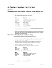
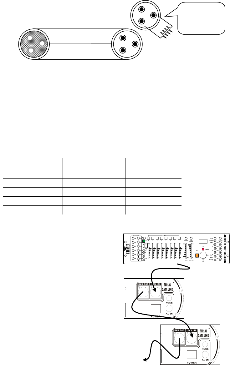
CABLE CONNECTORS
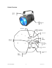
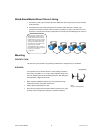
This drawing provides a
general illustration of the
DMX Input/Output panel of
a lighting fixture.
U X Controller niversal DM
Continue the link
Cabling must have a male XLR connector on one end and a female XLR connector on the other end.
can cause a ground loop, and your fixture may perform erratically. Test cables with an ohm meter to
r.
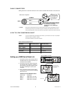
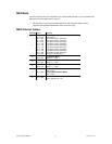
3-PIN TO 5-PIN CONVE
pin DMX output connector, you will need to use a 5 pin to 3 pin adapter.
CHAUVET Model No: DMX5M, or DMX5F.
3
PIN TO 5 PIN C
duc 3 Pin Female (output) 5 Pin Male (Input)
COMMON
DMX
+
DMX
-
INPUT OUTPUT
1
3
2
1
3
2
1
3
2
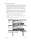
Resistance 120
ohm 1/4w between
pin 2 (DMX -) and
pin 3 (DMX +) of
the last fixture.
Termination reduces signal errors and
to avoid signal transmission problems
and interference, it is always
advisable to connect a DMX signal
terminator.
DMX connector configuration
CAUTION Do not allow contact between the common and the fixture’s chassis ground. Grounding the common
verify correct polarity and to make sure the pins are not
grounded or shorted to the shield or each othe
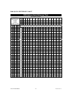
RSION CHART
Note! If you use a controller with a 5
The chart below details a proper cable co
nversion:
ONVERSION CHART
Con tor
Ground/Shield Pin 1 Pin 1
Data ( - ) signal Pin 2 Pin 2
Data ( + ) signal Pin 3 Pin 3
Do not use Do not use
Do not use Do not use
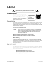
Setting up a DMX Serial Data Link
e of
pin
2.
a (female) 3
3. t
ove to the input of the following
escription
.5m/14.8ft
1. Connect the (male) 3 pin connector sid
the DMX cable to the output (female) 3
connector of the controller.
Connect the end
of the cable coming from
the controller which will have
pin connector to the input connector of the
next fixt
ure consisting of a (male) 3 pin
connector.
Then, proceed to connect from the outpu
as stated ab
fixture and so on.
CH
AUVET Certified DMX Data Cables
Order Code D
DMX1.5 DMX Cable 1.5m/4.9ft
DMX4.5
DMX Cable 4
DMX10 DMX Cable 10m/32.8ft
Vue™ II User Manual 8 2007-05-10/13:15