SKU 66891 For technical questions, please call 1-800-444-3353. Page 10
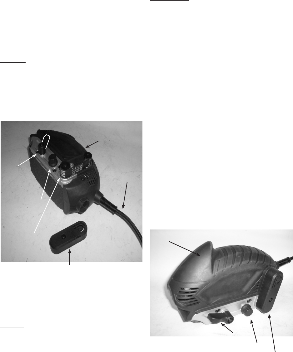
Rotate and position the Belt Release a.
-
lower Wheel (48) retracts and re-
moves the tension on the Sanding
Belt (38). See Figure 1.
Slide off the old/worn belt. b.
NOTE: While the grit of the sanding belt
may vary depending on what type of
cutting results you need for your proj-
ect, the size of the new belt should be
identical to the belt being replaced:
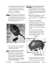
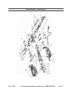
Drive Belt Cover (1)
Tracking
Knob (23)
Follower
Wheel
(48)
Belt
Re-
lease
Lever
(35)
Body
Housing
(49)
Power
Cord (66)
Figure 1
c. Slip a new belt around the Wheels
(33 & 48) and slide on until the
Wheels are covered.
NOTE: Sanding belts without directional
arrows may face either direction
(front or rear). If there are arrows
printed on the inside of the sand-
ing belt, make sure the arrows point
in the direction of Wheel rotation.
(Wheel rotation would be clockwise
when you are looking into the open
side of the Belt Sander).
WARNING! Severe laceration hazard!
If a directional sanding belt (one
with arrows printed on the inside), is
installed backwards, it may not track
properly and may overhang the Body
Housing (49) possibly causing severe
lacerations,
d.
“Down” to reapply tension to the
Sanding Belt (38). See Figures 1 &
2.
Tracking the Sanding Belt:2.
Tracking should be done with the a.
Compact Belt Sander running. The
easiest way to accomplish this is to
Sander and unplug it from its power
source.
Turn the Compact Belt Sander b.
upside down, place in a vise (not
included) large enough to hold it
securely, then plug it into a power
source and turn it “ON”.
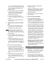
Figure 2
Body Housing (49)
Belt Release Lever (35)
Tracking Knob (23)
Drive Belt Cover (1)
c. Turn the Tracking Knob (23) coun-
terclockwise to move the sanding
belt toward the Body Housing (49),


