6
Step 3 To use Cisco Router and Security Device Manager (SDM) to configure your router, you must connect a PC to the first
Ethernet switch port. Connect one end of an Ethernet cable to one of the Ethernet switch ports (FE 2–FE 9), and connect
the other end to the Ethernet port on your PC.
Caution Always connect the Ethernet cable to an Ethernet port on the router. Accidentally connecting the cable to the wrong
port can damage your router.
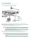
Step 4 To connect the router to your service provider network, connect one end of an Ethernet cable to a 10/100 Fast Ethernet
port (these ports are labeled FE 0 and FE 1); connect the other end of the cable to a network port on your service
provider’s broadband (xDSL or cable) modem equipment, as shown in Figure 2.
Caution Always connect the Ethernet cable to an Ethernet port on the router. Accidentally connecting the cable to the wrong
port can damage your router.
Step 5 (Optional) The Cisco 1811 router supports a 230-kbps dialup connection to your service provider network through its
V.92 modem port. The Cisco 1812 router supports a 144-kbps dialup connection to your service provider network
through its ISDN S/T port. These connections can serve as a backup to your service provider if your primary connection
goes down. To make a backup connection to your service provider network, connect one end of a straight-through
RJ-11 cable to the V.92 modem port (for the Cisco 1811) or a straight-through RJ45 cable to the ISDN S/T port (for
the Cisco 1812) on the router, as shown in Figure 2, and connect the other end of the cable to your telephone wall jack.
Note To configure your router for a backup dialup connection, you must use the Cisco IOS command-line
interface (CLI). For more information, see the Cisco 1800 Series Integrated Services Routers (Fixed) Software
Configuration Guide.
5 Connecting Antennas to the Router RP-TNC Connectors
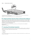
If your router has the wireless LAN option, connect the antennas by screwing the antenna connectors in a clockwise direction
onto the reverse-polarity threaded Neill-Concelman (RP-TNC) connectors on the back panel of the router. Figure 3 shows an
example of how to connect the swivel-mount dipole antennas to the router.
Note The location and position of your router antennas are crucial to effective wireless connectivity. For more information
about the antennas compatible with the Cisco 1801, Cisco 1802, and Cisco 1803 routers, see the online documents
located at the following URL:
http://www.cisco.com/univercd/cc/td/doc/product/access/acs_mod/1800fix/antennas/index.htm


