


Chapter 2 Installation
Optional Installation Steps
2-14
Cisco 1711 and Cisco 1712 Security Access Routers Hardware Installation Guide
OL-4050-02
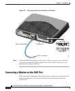
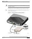
Step 2 Connect the DB-9 end of the cable to the DB-9 end of the DB-9-to-DB-25 adapter.
Step 3 Connect the DB-25 end of the adapter to the modem.
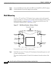
Wall-Mounting
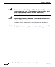
The Cisco 1711 and Cisco 1712 Security Access routers can be wall-mounted
using two number six, 3/4-inch screws and the molded mounting brackets on the
bottom of the hub, as shown in Figure 2-7. You must provide the screws. We
recommend using pan-head or round-head screws.
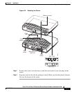
Figure 2-7 Wall-Mount Brackets—Bottom of Router
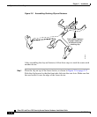
To mount the router on a wall or other surface:
Step 1 Install the two screws 3.75 inches (9.52 centimeters) horizontally apart on a wall
or other vertical surface.
The screws should protrude 0.25 inch (0.64 centimeter) from the surface of the
wall.
Front panel of router
12016
3.75"
(9.52 cm)
Mounting
bracket
Mounting
bracket
Mounting
bracket
Bottom
of router
Mounting
bracket