


5
4 Connecting the Router
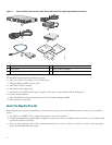
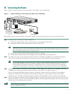
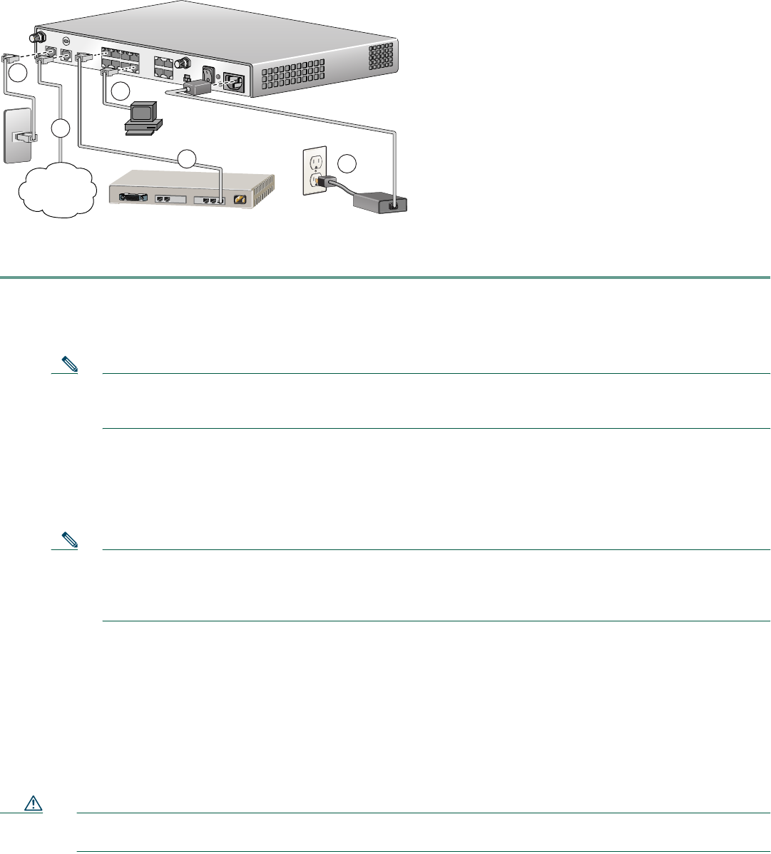
Figure 2 shows a typical installation of the Cisco 1801, Cisco 1802, or Cisco 1803 router.
Figure 2 Typical Installation of a Cisco 1801, Cisco 1802, or Cisco 1803 Router
Follow these steps to connect the router to the power supply, your local network, and your service provider network:
Step 1 Connect power to the router as shown in Figure 2:
a. Connect the separate power cord to the power socket on the back panel of the router.
b. Connect the other end of the separate power cord to a power outlet.
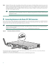
Note If you have a router with the PoE option, you must connect the PoE power supply to the PoE socket on the
back of the router, connect the female end of the PoE power cable to the PoE power supply, and connect the
male end of the PoE power cable to a power outlet.
c. Turn on the router by pressing the power switch to the on ( | ) position.
d. Confirm that the router has power by checking that the SYS OK LED on the front panel is on.
Step 2 To connect the router to your network, connect one end of an Ethernet cable (RJ-45) to an Ethernet switch port
(FE 1–FE 8), and connect the other end of the cable to a port on a hub or switch, as shown in Figure 2.
Note The example in Figure 2 shows connectivity to a hub. The router Ethernet switch ports can be connected to
another networked device, such as a switch or computer with a network interface card (NIC). If you are
connecting the switch port on the router to another switch, use a crossover cable. If you are connecting a
computer to the switch port on the router, it will take about 30 seconds for connectivity to be established.
Step 3 To connect the router to an xDSL line, connect either an ADSL cable to the ADSL port or a G.SHDSL cable to the
G.SHDSL port, and connect the other end of the cable to your xDSL line as shown in Figure 2.
See the “Connecting DSL WAN Interface Cards to a Network” chapter in the Cisco Interface Cards Hardware
Installation Guide for more information about cabling the xDSL port. This document is located at this URL:
http://www.cisco.com/univercd/cc/td/doc/product/access/acs_mod/cis2600/hw_inst/wic_inst/wic_doc/wandsl.htm
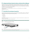
Step 4 To use Cisco Router and Security Device Manager (SDM) to configure your router, you must connect a PC to the first
Ethernet switch port. Connect one end of an Ethernet cable to one of the Ethernet switch ports (FE 1–FE 8), and connect
the other end to the Ethernet port on your PC.
Caution Always connect the Ethernet cable to an Ethernet port on the router. Accidentally connecting the cable to the wrong
port can damage your router.
Ethernet Hub
Power Supply
121547
3
1
2
4
Internet
Service
Provider
5