


8
Verifying the LEDs
78-6379-03
Verifying the LEDs
Verifying the LEDs
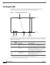
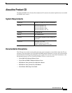
Verify the power, Ethernet, and serial connections by checking the LEDs. Figure 6 shows the
components that you must verify and the location of their corresponding LEDs.
Figure 6 Components and Associated LEDs
The following table describes the normal pattern for these LEDs and what to do if you get an abnormal
pattern. For more information on all LEDs, see Chapter 1, “Product Overview” of the Cisco 805 Router
Hardware Installation Guide.
LED
Normal
Pattern Explanation If Abnormal Pattern
OK On Power is supplied to the
router.
If off, see Chapter 3, “Troubleshooting” in the
Cisco 805 Router Hardware Installation Guide.
LINK On Ethernet device is
connected.
If off, toggle HUB/NO HUB button (if set to HUB
[in], reset to NO HUB [out] or vice versa).
1
If still
off, see Chapter 3, “Troubleshooting” in the Cisco
805 Router Hardware Installation Guide.
1. For information on how the setting of this button on a hub affects the setting of the router HUB/NO HUB button, see Chapter
2, “Installing the Cisco 805 Router” in the Cisco 805 Router Hardware Installation Guide.
CD
(Carrier
detect)
On Packets are sent or received
from serial port.
2
2. The CD LED will not light until you configure the serial interface. For more information on configuring the serial interface,
see the Cisco 805 Router Software Configuration Guide.
If off for a long time, see Chapter 3,
“Troubleshooting” in the Cisco 805 Router
Hardware Installation Guide.
CD LED
Front panel
Power connector
and switch
OK LED
Back panel
Serial
port
Ethernet
port
LINK
LED