


15
Performance Route Processor Installation and Configuration Guide
OL-11656-01
Product Overview
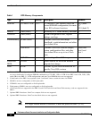
The PRP-2 has the following LED indicators:
• Two Flash disk activity LEDs, one for each Flash disk slot (labeled SLOT-0
and SLOT-1)—Indicate when the Flash disk slot is accessed.
• Two Ethernet port LEDs used in conjunction with each of the three RJ-45
Ethernet connectors:
–
LINK—indicates link activity
–
DATA—indicates data transmission or reception
• Two BITS port LEDs used in conjunction with each of the two BITS ports:
–
SIG—indicates carrier signal available
–
ACT—indicates the interface is active
Display LEDs
The alphanumeric display LEDs are organized as two rows of four characters each
and are located at one end of the card. These LEDs provide system status and error
messages that are displayed during and after the boot process. The boot process
and the content displayed are controlled by the MBus module software of the PRP.
At the end of the boot process, the LEDs are controlled by the Cisco IOS software
(via the MBus), and the content displayed is designated by the Cisco IOS
software.
A complete, descriptive list of all system and error messages is located in the
Cisco IOS System Error Messages publications.
The display LEDs indicate the following:
• Status of the PRP
• System error messages
• User-defined status/error messages