


5
Nothing Comes Close to a Cobra
™
4
Quick Evaluation
Before Installation
I
ntro Operation Customer
Assistance
W
arranty
Notes
Notice
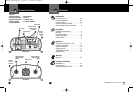
Main Icons
Secondary Icons
Caution Warning
I
nstallation
Introduction
Quick Evaluation
Before Installation
I
ntro Operation Customer
Assistance
W
arranty
Notes
Notice
Main Icons
Secondary Icons
Caution Warning
I
nstallation
Introduction
Quick Evaluation Before Installation
•
This section provides you with basic information about the
inverter and how to check its performance before installation.
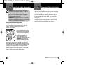
Be sure to have on hand:
A 12 volt DC power source (such as a vehicle battery).
The power source must provide
between 11 and 15 volts DC and
be able to supply enough current to
run the test load. As a rough guide,
divide the wattage of the test load by
10 to get the current (in amperes)
the power source must deliver.
Cables to connect the power source to the inverter.
Cables are supplied with the unit that are two feet
long overall from the tip of the clamp shown to the
stripped and tinned end for insertion in the Input
End of the unit.
If user supplied cables are to be used, they must be
as short and thick as possible in order to reduce the
voltage drop between the power source and the inverter
when it is drawing current from the power source.
If the cable suffers an excessive voltage drop, the inverter
may shut down when drawing higher currents because
the voltage at the inverter dropped below 10 volts.
A test load that can be plugged into the AC receptacle on
the inverter for short term testing at a low power level.
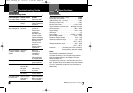
The following cables are recommended for testing low
power level test loads only.
Test Load Minimum
Power Cable Size
100W # 16 AWG copper
250W # 12 AWG copper
500W # 8 AWG copper
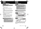
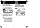
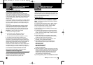
P
ower Source
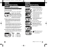
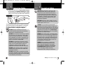
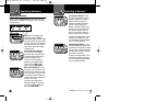
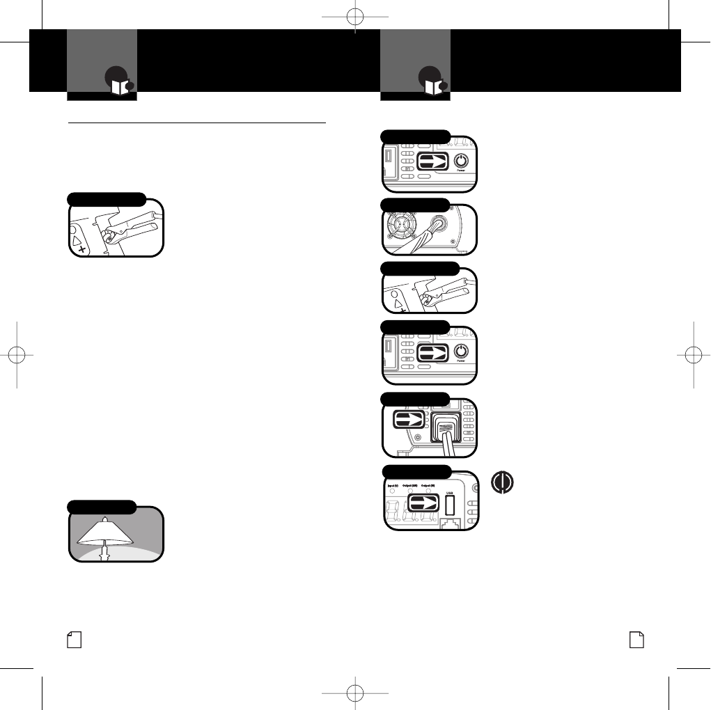
To check your inverter’s performance before installation:
1.Turn the inverter off (see page 14
for details). If the power source is
a DC power supply, switch it off
as well.
2.Connect cables to power input
terminals (see page 8 for details).
3.Connect cables to power source
(see page 8 for details).
4.Check to make sure all
connections are secure.
5.Turn the inverter on. If the power
source is a DC power supply,
switch it on first.
6.Plug in the test load.
The inverter should supply power
to the load. If the inverter is not
working properly, refer to the
troubleshooting guide on page 20
or power and protection indicators
section on page 16.
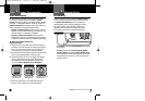
NOTE A USB device can be
used to check the output
of the USB Outlet.
Intro Operation Customer
Assistance
Warranty
Notes
Notice
Main Icons
Secondary Icons
Caution Warning
Installation
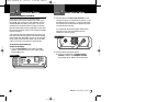
T
est Load
Power Button
Connect Terminals
Power Button
Connect Test Load
USB Outlet
Connect Power Source
Intro Operation Customer
A
ssistance
Warranty
Notes
Notice
Secondary Icons
Caution Warning
Installation
I
ntro Operation Customer
Assistance
W
arranty
Notes
Notice
Main Icons
Secondary Icons
Caution Warning
Installation
Intro Operation Customer
Assistance
Warranty
Notes
Notice
M
ain Icons
Secondary Icons
Caution Warning
I
nstallation
Intro Operation Customer
Assistance
Warranty
Notes
Notice
Main Icons
Secondary Icons
Caution Warning
Installation
10274_CPI1000_vC 8/14/07 3:48 PM Page 4