


9
15G HANDLE
NAME OF PART QTY.
1
1
1
1
1
2
1
1
1
1
NAME OF PARTPART NO. QTY.
1
1
1
1
1
1
1
1
1
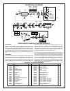
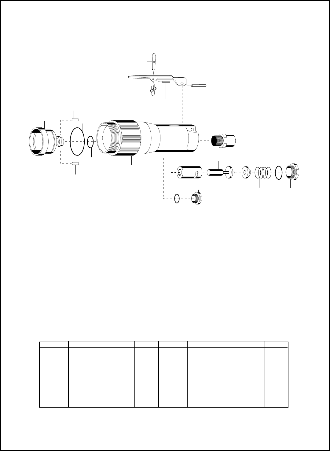
The complete handle assembly can be purchased using Part No. 201019.
The lock-off lever can be purchased as a subassembly using Part No. 861992.
PARTS LIST — 15G HANDLE
PART NO.
202105
202106
202337
832595
841552
843590
844304
844311
845409
847710
847808
863093
864375
864387
864530
864531
865698
865701
869855
Toggle
Lock-Off Lever
Throttle Valve
Throttle Valve Spring
Inlet Bushing
Oiler Valve
"O"-Ring 7/32' x 11/32"
"O"-Ring 9/16" x 3/4"
Toggle Pin
"O"-Ring 1/2" x 5/8"
Throttle Lever Pin
"O"-Ring 1" x 1-1/8"
Throttle Valve Seal
Oil Fill Plug
Valve Bushing
Valve Cap
Oiler Body (Incl.843590)
Backhead (Incl.864530)
Toggle Spring
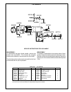
DISASSEMBLY
To disassemble the lever throttle handle, unscrew the
throttle valve cap 864531. This will allow the complete
throttle valve assembly to be removed from the handle.
The oiler body on the handle may be removed from the front
of the handle with the aid of spreaders.
REASSEMBLY
The handle is reassembled in the reverse order of disas-
sembly. All parts should be inspected for damage or wear.
Should a throttle valve bushing need replacing, be sure to
align air ports. Air screens should be cleaned and replaced
if torn.
SERVICE INSTRUCTIONS FOR 15G HANDLE
869856
869855
865701
847808
841552
844304
832595
864531
843590
844311
202105
202106
843590
865698
863093
864387
864530
202337
864375
847710