


CAUTION: Strobes are not designed to be used on coded systems in which the applied voltage is cycled on and off.
WARNING: MAKE SURE THAT THE TOTAL RMS CURRENT REQUIRED BY ALL APPLIANCES THAT ARE CONNECTED TO THE
SYSTEM’S PRIMARY AND SECONDARY POWER SOURCES, NOTIFICATION APPLIANCE CIRCUITS, SM, DSM SYNC MODULES, OR
COOPER WHEELOCK POWER SUPPLIES DOES NOT EXCEED THE POWER SOURCES’ RATED CAPACITY OR THE CURRENT RATINGS
OF ANY FUSES ON THE CIRCUITS TO WHICH THESE APPLIANCES ARE WIRED. OVERLOADING POWER SOURCES OR EXCEEDING
FUSE RATINGS COULD RESULT IN LOSS OF POWER AND FAILURE TO ALERT OCCUPANTS DURING AN EMERGENCY, WHICH
COULD RESULT IN PROPERTY DAMAGE AND SERIOUS INJURY OR DEATH TO YOU AND/OR OTHERS.
WIRING AND MOUNTING INFORMATION:
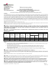
CAUTION: The following figure shows the maximum number of field wires (conductors) that can enter the backbox used with each mounting option. If
these limits are exceeded, there may be insufficient space in the backbox to accommodate the field wires and stresses from the wires could damage the product.
CAUTION: Check that the installed product will have sufficient clearance and wiring room prior to installing backboxes and conduit, especially if sheathed
multiconductor cable is used.
Although the limits shown for each mounting option comply with the National Electrical Code (NEC), Cooper Wheelock recommends use of the largest backbox
option shown and the use of approved stranded field wires, whenever possible, to provide additional wiring room for easy installation and minimum stress on the
product from wiring.
MAXIMUM NUMBER OF CONDUCTORS
AWG#18 AWG#16 AWG#14 AWG#12
4
4
4
4
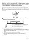
SURFACE (INDOOR/OUTDOOR)
MOUNTING TAB
(SUPPLIED)
WPSBB
#8-18 SCREWS
WOOD SCREWS
WARNING: THIS UNIT MUST BE MOUNTED ON A FLAT SURFACE, SO THAT THE SURFACE COVERS THE ENTIRE BACK SURFACE
OF THE BACKBOX. WHEN USED IN AN OUTDOOR APPLICATION OR A NEMA 3R APPLICATION, USE WEATHER PROOF RATED
CONDUIT FITTING ON ALL KNOCKOUTS OF THE BACKBOX.
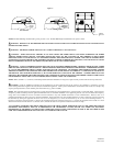
Figure 1: Wiring Diagram
OR END OF LINE
FROM PRECEDING
APPLIANCE, FACP
TO NEXT SIGNAL
+
-
STROBES
RESISTOR (EOLR)
OR SYNC MODULE
Figure 2:
• All strobes have in-out wiring terminals that accepts two #12 to #18 American Wire Gauge
(AWG) wires at each screw terminal. Strip leads 3/8 inches and connect to screw terminals.
• Break all in-out wire runs on supervised circuits to assure integrity of circuit supervision as
shown in Figure 2. The polarity shown in the wiring diagrams is for the operation of the
appliances. The polarity is reversed by the FACP during supervision.
Refer to instruction sheets for SM (P83123), DSM (P83177) or Cooper Wheelock power supplies for additional information.
1. The knock-out opening on the backbox is sized for a ½” conduit and matching connector. Be sure that a proper watertight conduit fitting is used to
connect the backbox for outdoor/severe environment applications. Conduit entrances to the backbox should be selected to provide sufficient wiring
clearance for the installed product. Do not pass additional wires (used for other than the signaling appliance) through the backbox. Such additional
wires could result in insufficient wiring space for the signaling appliance.
2. When terminating field wires, do not use more lead length than required. Excess lead length could result in insufficient wiring space for the
appliance.
3. Use care and proper techniques to position the field wires in the backbox so that they use minimum space and produce minimum stress on the product.
This is especially important for stiff, heavy gauge wires and wires with thick insulation or sheathing.
4. Connect 4 field wires to the RSSWP terminal block (polarity must be observed).
5. Bend the 4 field wires up 90° at the connection to the terminal block, then carefully push the 4 field wires into the backbox by hand.
6. Carefully press the RSSWP to the backbox, verifying that the RSSWP is in contact with the gasket all the way around. It should not be resting on the
lip of the backbox.
7. Screw the RSSWP to the WPSBB using the #8-18 screws supplied.
P84824 D
Sheet 2 of 4