


• Form a loop by forcing end with round holes through
slotted hole opposite end.
• Place the loop over the cord and pull it tight.
• Mount the chuck key by inserting the geared end
through the hole in the holder. Large keys in the
larger hole, smaller keys in the small hole.
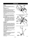
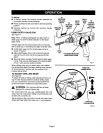
VARIABLE SPEED
See Figure 5.
Your hammer drill has a variable speed control switch
that delivers higher speed with increased trigger pres-
sure. Speed is controlled by the amount of switch
trigger depression.
Avoid running your hammer drill at low speeds for
extended periods of time. Running at low speeds under
constant usage may cause your drill to become over-
heated. If this occurs, cool your drill by running it
without a load and at full speed.
The following guidelines may be used in determining
correct speed for various applications:
• Low speed is ideal when minimum speed and power
is required. For example: starting holes without
center punching, driving screws, mixing paint, and
drilling in ceramics.
• Medium speed is suitable for drilling hard metals,
plastics, and laminates.
• High speed produces best results when maximum
power is required. For example: drilling inwood, soft
metals such as aluminum, brass, and copper, and
when using driving accessories.
_ WARNING: Your hammer drill should never be
connected to power supply when you are assem-
bling parts, making adjustments, installing or
removing drill bits, or when not in use. Discon-
necting your drill will prevent accidental starting
that could cause serious injury.
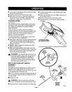
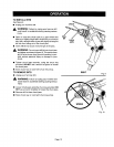
INSTALLING AUXILIARY HANDLE
ASSEMBLY
See Figure6.
An auxiliary handle is packed with yourdrillfor ease of
operation and to help prevent loss of control,The
handle can be rotated 360° and it can also be mounted
on the opposite side for left hand use.
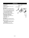
Note: For convenience and ease of starting threads, the
hex nut has been trapped inside the molded slot in the
auxiliary handle.
• Unplug your drill.
,_ WARNING: Failure to unplug your drill could
result in accidental starting causing serious injury.
• Remove auxiliary handle assembly from plastic bag.
Page 8
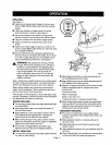
• Loosen handle enough to make opening large enough
to fit over chuck.
• Slide ring of handle over chuck. Note: Handle fits on
neck of gear housing.
• Rotate handle to desired operating position.
• Securely tighten by turning the auxiliary handle
clockwise.
TO INCREASESPEED,
PULLSWITCHTRIGGER
Fig. 5
GAGEROD
TEETH
TEETH
INDICATOR
GEAR
HOUSING
DEPTH
GAGECLAMP
DEPTH
GAGEROD
AUXILIARY
HANDLE
ASSEMBLY
Fig. 6