


12 - ENGA17883
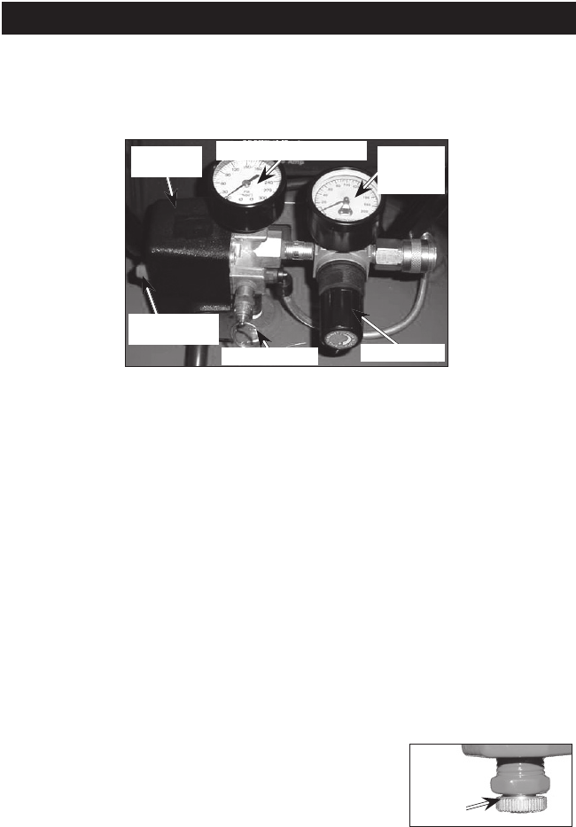
Regulator: Controls the air pressure
shown on the outlet pressure gauge.
Turn regulator knob clockwise to
increase pressure and counterclock-
wise to decrease pressure.
Cooling System (not shown): This
compressor contains an advanced
design cooling system. At the heart of
this cooling system is an engineered
fan. It is perfectly normal for this fan
to blow air through the vent holes
in large amounts. You know that the
cooling system is working when air is
being expelled.
Air Compressor Pump (not shown):
Compresses air into the air tank.
Working air is not available until the
compressor has raised the air tank
pressure above that required at the air
outlet.
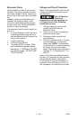
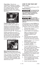
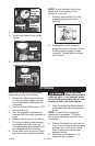
Drain Valve:
Drain
Valve
The drain valve
is located at
the base of the
air tank and is
used to drain
condensation at the end of each use.
Description of Operation
Become familiar with these controls
before operating the unit.
On/Auto/Off Lever: Place this switch
in the "On/Auto" position to provide
automatic power to the pressure
switch and "Off" to remove power at
the end of each use.
Pressure Switch (not shown): The
pressure switch automatically starts
the motor when the air tank pressure
drops below the factory set "cut-in"
pressure. It stops the motor when the
air tank pressure reaches the factory
set "cut-out" pressure.
Safety Valve: If the pressure switch
does not shut "Off" the air compres-
sor at its "cut-out" pressure setting,
the safety valve will protect against
high pressure by "popping out" at its
factory set pressure (slightly higher
than the pressure switch "cut-out"
setting).
Tank Pressure Gauge: The tank
pressure gauge indicates the reserve
air pressure in the tank.
Outlet Pressure Gauge: The outlet
pressure gauge indicates the air pres-
sure available at the outlet side of the
regulator. This pressure is controlled
by the regulator and is always less
than or equal to the tank pressure.
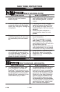
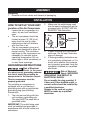
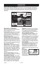
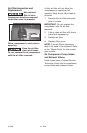
OPERATION
Know Your Air Compressor
READ THIS OWNER’S MANUAL AND SAFETY RULES BEFORE OPERATING
YOUR UNIT. Compare the illustrations with your unit to familiarize yourself with
the location of various controls and adjustments. Save this manual for future
reference.
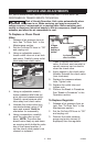
Safety Valve
On/Auto/Off
Switch
Regulator
Outlet
Pressure
Gauge
Tank Pressure Gauge
Pressure
Switch