


14- ENG
D29495
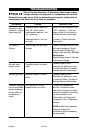
Female Tire Chuck: Attaches to the
hose end to be used to inflate tires.
Note: To ensure correct tire pressure
use a tire pressure gauge.
Hose Adapter: Attaches to hose end
to allow the use of accessories.
Blow Gun Adapter: Attaches to hose
end or blow gun (sold separately, not
shown) to allow the inflating needle
to be used.
Inflating needle: Attaches to blow
gun adapter to be used to inflate
sport balls.
Tapered Inflator: Attaches to hose
adapter or blow gun (sold separately)
to be used to inflate toy inflatables/air
mattresses.
Extension Tube: Attaches to hose
adapter or blow gun (sold separately)
to be used for air blowing, drying,
and for specialized inflating.
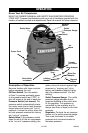
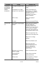
Drain Valve (not shown): The drain
valve is located at the base of the air
tank and is used to drain
condensation at the end of each use.
Cooling System (not shown): This
compressor contains an advanced
design cooling system. At the heart
of this cooling system is an
engineered fan. It is perfectly normal
for this fan to blow air through the
vent holes in large amounts. You
know that the cooling system is
working when air is being expelled.
Air Compressor Pump (not shown):
Compresses air into the air tank.
Working air is not available until the
compressor has raised the air tank
pressure above that required at the
air outlet.
Check Valve (not shown): When the
air compressor is operating, the
check valve is "open", allowing
compressed air to enter the air tank.
When the air compressor reaches
"cut-out" pressure, the check valve
"closes", allowing air pressure to
remain inside the air tank.
How to Use Your Unit
How to Stop:
1. Set the Off/Auto switch to "OFF".
Before First Start-up
Break-in Procedure
Risk of Unsafe
Operation. Serious
damage may result if the following
break-in instructions are not
closely followed.
This procedure is required before the
air compressor is put into service.
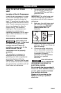
1. Make sure the Off/Auto switch is
in the "OFF" position.
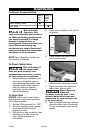
2. Turn the regulator knob
counterclockwise until it stops.
3.
Plug the power cord into the
correct branch circuit receptacle.
(Refer to Voltage and Circuit
Protection paragraph in the
Installation section of this
manual.)
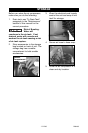
4. Open the drain valve fully
(counterclockwise) to permit air
to escape and prevent air
pressure build up in the air tank
during the break-in period.
5. Move the Off/Auto switch to
"AUTO" position. The
compressor will start.
6. Run the compressor for 15
minutes. Make sure the drain
valve is open and there is
minimal air pressure build-up in
tank.
7. After 15 minutes, close the drain
valve (clockwise). The air receiver
will fill to "cut-out" pressure and
the motor will stop.
The compressor is now ready for use.