


Glossary
CFM: Cubic feet per minute
SCFM: Standard cubic feet per minute; a unit of measure
for air delivery.
PSlG: Pounds per square inch gauge; a unit of measure
for pressure.
ASME: American Society of Mechanical Engineers.
California Code: Unit may comply with California Code
462 (I) (2)/(M) (2).
Cut-In Pressure: The air compressor will automatically
start to refill the tank when the pressure drops
below the prescribed minimum.
Cut-Out Pressure: The point at which the motor stops
when the tank has reached maximum air
pressure.
Code Certification: Products that bear one or more of
the following marks: UL, CUL, ETL, CETL, have
been evaluated by OSHA-certified independent
safety laboratories and meet the applicable
Underwriters Laboratories Standards for Safety.
Duty Cycle
This is a 50% duty cycle air compressor. Do not run the air compressor more than 30 minutes of one hour. Doing so
could damage the air compressor.
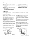
Parts & Features
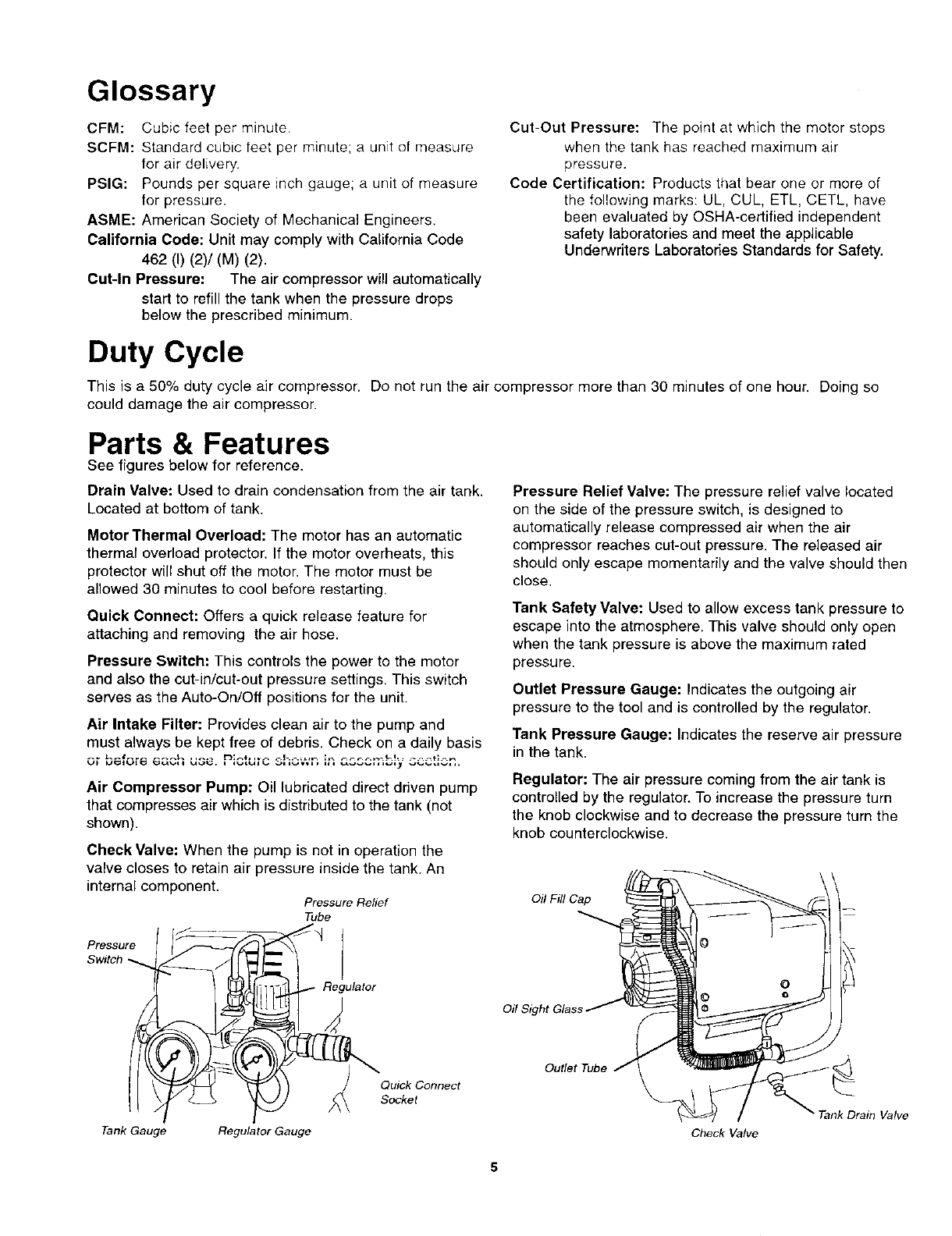
See figures below for reference.
Drain Valve: Used to drain condensation from the air tank.
Located at bottom of tank.
Motor Thermal Overload: The motor has an automatic
thermal overload protector. If the motor overheats, this
protector will shut off the motor. The motor must be
allowed 30 minutes to cool before restarting.
Quick Connect: Offers a quick release feature for
attaching and removing the air hose.
Pressure Switch: This controls the power to the motor
and also the cut-in/cut-out pressure settings. This switch
serves as the Auto-On/Off positions for the unit.
Air Intake Filter: Provides clean air to the pump and
must always be kept free of debris. Check on a daily basis
Air Compressor Pump: Oil lubricated direct driven pump
that compresses air which is distributed to the tank (not
shown).
Check Valve: When the pump is not in operation the
valve closes to retain air pressure inside the tank. An
internal component.
Pressure Relief
Tube
-- -_ _
Pressure _
Switch
lii-_ _ Regulator
_ _ _Quick ConneCtsocket
Tank Gauge Regulator Gauge
Pressure Relief Valve; The pressure relief valve located
on the side of the pressure switch, is designed to
automatically release compressed air when the air
compressor reaches cut-out pressure. The released air
should only escape momentarily and the valve should then
close.
Tank Safety Valve: Used to allow excess tank pressure to
escape into the atmosphere. This valve should only open
when the tank pressure is above the maximum rated
pressure.
Outlet Pressure Gauge: Indicates the outgoing air
pressure to the tool and is controlled by the regulator.
Tank Pressure Gauge: Indicates the reserve air pressure
in the tank.
Regulator; The air pressure coming from the air tank is
controlled by the regulator. To increase the pressure turn
the knob clockwise and to decrease the pressure turn the
knob counterclockwise.
Oil Fill Cap
Oil Sight Glass
Outlet Tube
Valve
Check Valve