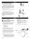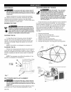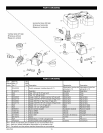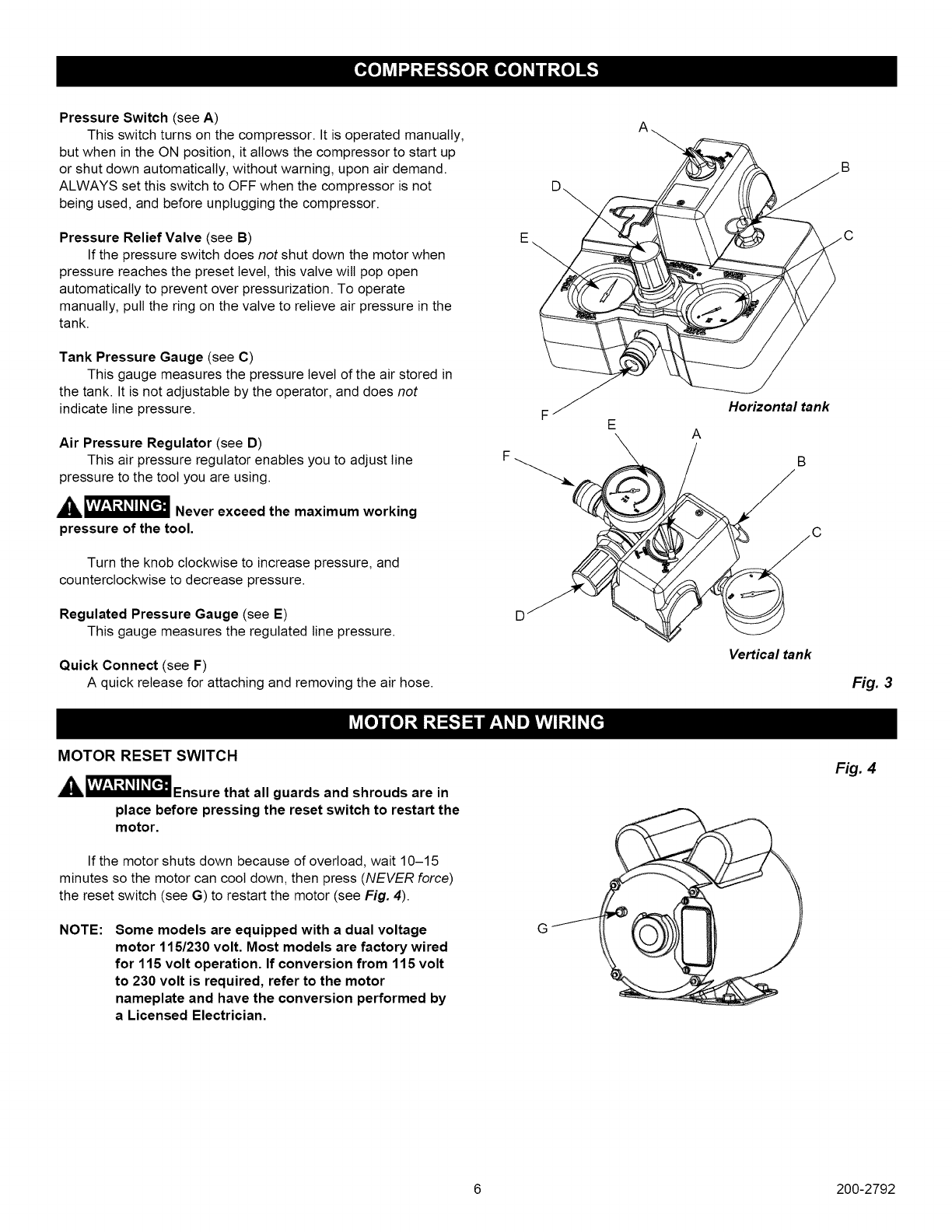
Pressure Switch (see A)
This switch turns on the compressor. It is operated manually,
but when in the ON position, it allows the compressor to start up
or shut down automatically, without warning, upon air demand.
ALWAYS set this switch to OFF when the compressor is not
being used, and before unplugging the compressor.
Pressure Relief Valve (see B)
If the pressure switch does not shut down the motor when
pressure reaches the preset level, this valve wilt pop open
automatically to prevent over pressurization. To operate
manually, pull the ring on the valve to relieve air pressure in the
tank.
Tank Pressure Gauge (see C)
This gauge measures the pressure level of the air stored in
the tank. It isnot adjustable by the operator, and does not
indicate line pressure.
Air Pressure Regulator (see D)
This air pressure regulator enables you to adjust line
pressure to the tool you are using.
__ Never exceed the maximum working
pressure of the tool.
Turn the knob clockwise to increase pressure, and
counterclockwise to decrease pressure.
Regulated Pressure Gauge (see E)
This gauge measures the regulated line pressure.
Quick Connect (see F)
A quick release for attaching and removing the air hose.
B
Horizontal tank
A
B
Vertical tank
Fig. 3
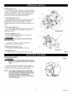
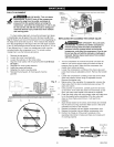
MOTOR RESET SWITCH
__Ensure that all guards and shrouds are in
place before pressing the reset switch to restart the
motor.
If the motor shuts down because of overload, wait 10-15
minutes so the motor can cool down, then press (NEVER force)
the reset switch (see G) to restart the motor (see Fig. 4)
NOTE:
Some models are equipped with a dual voltage
motor 115/230 volt. Most models are factory wired
for 115 volt operation. If conversion from 115 volt
to 230 volt is required, refer to the motor
nameplate and have the conversion performed by
a Licensed Electrician.
G
Fig. 4
6 200-2792


