


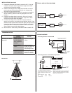

WIRING DIAGRAMS
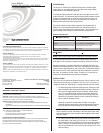
60°
Field-of-View
INSTALLATION (Continued)
3. Prepare the photocell lead wires by removing 3/4" (1.9 cm) of
insulation from each lead to expose bare copper wire. Make
sure the ends of wires are straight.
4. Determine the length of low voltage wires needed to connect
power to photocell. Use wires suitable for low-voltage wiring
according to local electrical codes.
5. Route low-voltage wires from GLS-LCL location(s) to interface
device location(s). (Refer to the wiring diagrams in the next
column.)
6. Prepare low-voltage wires by removing 3/4 inch (1.9 cm) of
insulation from each lead to expose bare copper wire. Make
sure the ends of the wires are straight.
7. Connect low voltage wires as shown in Figure 2 (black to
ground, red to power, and orange to the interface device). Twist
strands of each separate wire connection tightly, and push firmly
into appropriate wire connector. Screw connector on clockwise
ensuring no bare conductor shows below the wire connectors.
Secure each connector wiith electrical tape.
8. Mount GLS-LCL to the ceiling. INSTALLATION IS COMPLETE.
TROUBLESHOOTING
PROBLEM
POSSIBLE
CAUSE
CORRECTIVE
ACTION
Incorrect wiring
between sensor
and GLS-SIM (or
other compatible
interface).
Improper sensor
location.
Verify that sensor is
located such that it can
detect the desired
workspace light levels.
Lights don’t respond
to change in ambient
light level.
Improper control
system programming.
Check logic in control
processor, or contact
Crestron for assistance.
24 1 2 G
Black
Red
Orange
Black
Red
Connecting Sensors to the GLS-SIM
Connecting Sensors to the DIN-IO8 or Equivalent*
All wires from sensor to GLS-SIM
must be 24 AWG, minimum.
–SENSOR–
––– NET–––
24 Y Z G
Use CRESNET
-
P or
CRESNET
-
NP wire only
GLS-SIM
To Control
System
G 1 2 3 4
–––
NET
G 1 2 3 4
24 Y Z G
24 Y Z G
–––
To Control
System
–––
–––
I/O
DIN-IO8
NOTE: The same Crestron power supply MUST be
used to power both the sensors and the interface
device (e.g., DIN-IO8). Otherwise, there is a risk of
damage to the interface device.
*The following Crestron devices may be
used to integrate the sensors into a Cresnet
system by following the schematic shown
here:
DIN-IO8 DIN-AP2 PAC2 PRO2
AV2 CP2E MP2E CNXIO16
Use CRESNET
-
P or
CRESNET
-
NP wire only
TYPICAL APPLICATION DIAGRAMS
GLS-LCL
GLS-LCL
GLS-SIM
Cresnet
®
DIN-IO8
Cresnet
®
Crestron
2-Series Control
Processor or
CLS-C6
Crestron
2-Series Control
Processor
Orange
Refer to the wiring
diagrams in the right
column.
White**
Red**
Blue**
** 250 feet max.