


OPERATION
ADAPTIVE FUNCTIONS
ADJUSTMENT KNOB AND SWITCH SETTINGS
.
.
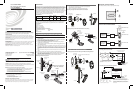
Adjustment Knob Settings
KNOB
COLOR
FUNCTION
Sets the ultrasonic range
Sets the infrared range
Delayed- Off Time
Ambient Light Override
(Gray wire only)
KNOB SETTING
Range setting
Full CCW = min. (OFF)
Full CW = max.
Range setting
Full CCW = min. (OFF)
Full CW = max.
Full CCW = min. (30 sec.)
Full CW = max. (30 min.)
DEFAULT
SETTING
75%
75%
100%
Full CCW – Lights stay OFF
Full CW – Lights always turn ON
(NO ambient light override)
Range– 100-3000 LUX
50%
(10 min)
Blue
Black
Red
Green
SYMBOL
Minimum and Default Settings
• Dual-Tech Mode. This is the default mode of operation for the sensor. Passive
infrared technology (PIR) turns lights on in this mode; however, motion detection by
either technology (PIR or ultrasonic) will keep the lights on. If neither technology
detects motion, the lights turn off after the delayed-off time.
• Single-Tech Mode. Only one technology is active in this mode. The technology is
selected by the dip switches. Motion detection by the selected technology - PIR or
ultrasonic - will turn on the lights as well as keep them on. When motion is not
detected, the lights will turn off after the delayed-off time.
• Delayed-Off Time. The sensor is designed to turn the lights off if no motion is
detected after a specified time. This length of time is called the delayed-off time and
is set using the timer (black) knob on the sensor. The adapting patterns will modify
the delayed-off time to fit the parameters of each installation based on
environmental conditions and occupancy patterns.
• Walk-through Mode. The walk-through feature is useful when a room is
momentarily occupied. With this feature, the sensor will turn the lights off shortly
after the person leaves the room.
The walk-through feature works as follows: When a person enters the room, the
lights will turn on. If the person leaves the room before the default walk-through
time-out of 2.5 minutes, the sensor will turn the lights off. If the person stays in the
room for longer than 2.5 minutes, the sensor will proceed to the Occupied mode.
• LED Operation. There are two LED indicators that will flash when motion is
detected. The LED flash can be disabled using the LED disable switch setting.
Green flash indicates motion detection by ultrasonic technology. Red flash indicates
motion detection by infrared technology.
The sensor continually analyzes the parameters of the motion detection signal and
adjusts its internal operation to maximize detection of motion while minimizing the effects
of noise (electrical noise, air currents, temperature changes, etc.).
Operation
When the lights turn on, the sensor initially starts the Walk-through mode. Once the room
is occupied for longer than 2.5 minutes, the sensor ends the Walk-through mode and
begins the Occupied mode. When the sensor is first installed, the delayed-off time for the
Occupied mode is based on the time adjustment settings. While the sensor is in use, the
delayed-off time will change, based on how the sensor adapts to the room conditions.
Whenever the sensor subsequently turns on, the value of the delayed-off time will be the
adapted value (refer to Occupancy Pattern Learning For Delayed Off Time).
The adapted settings can be reset using the DIP switch.
Occupancy Pattern Learning For Delayed Off Time
The sensor will automatically change the delayed off time in response to the occupancy
and environmental conditions of the space where it is installed. The sensor analyzes the
motion signal properties and will minimize the delayed off time duration when there is
frequent motion detection, and lengthen the delayed off time duration when there is weak
and infrequent motion detection.
In the case of a false-off condition (lights turn off when the room is occupied), the delayed
off time duration will immediately be lengthened to prevent further false turn offs.
Occupancy Pattern Learning for Ultrasonic Technology
The sensor learns the occupancy patterns of a space during the course of a day, for a
seven day period. At any given time, the sensor will look at the collected data and adjust
its ultrasonic sensitivity. The sensor will adjust the sensitivity to make it less likely to turn
on during a period of non-occupancy and more likely to turn on during a period of
occupancy. This adapting feature is not applicable when the sensor is using PIR functions
only.
The two tables (below and in the next column) and the “Minimum and Default Settings”
illustration define the settings of the adjustment knobs and the DIP switches.
* This setting is only used if the Single Technology Option (Switch A1) is selected.
SWITCH FUNCTIONS
Bank A OFF ON
Single/Dual-Tech Mode Dual-Tech Single Tech
PIR/Ultrasonic Mode PIR Ultrasonic
Manual Mode Auto Adapting Enabled Auto Adapting Disabled
Walk-Through Disable Walk-Through Enabled Walk-Through Disabled
Bank B
Override to ON Auto Mode Lights Forced ON
Override to OFF Auto Mode Lights Forced OFF
Test Mode OFF ON OFF = Enter/Exit Test Mode
LEDs Disable LEDs Enabled LEDs Disabled
DIP Switch Settings
SWITCH SETTINGS
SWITCH
A1
A2
*
A3
A4
B1
B2
B3
B4
Field-of-View Ranges - GLS-ODT-W-1200
TEST MODE
1. ENSURE POWER IS ON.
2. Remove front cover.
3. Locate Dip Switch 3 in Bank B (B3). B3 will be in the OFF position from the factory.
4. To start Test Mode, move switch to ON and back to OFF. The test mode has now
been initiated with a six second time-out. (Refer to the DIP Switch Settings table.)
NOTE: If B3 is already in the ON position, then Test mode can be entered by just moving it
to the OFF position.
NOTE: The timer will remain in the six second Test mode for 15 minutes, then
automatically exit Test mode and reset to the delayed-off time setting as defined by the
black timer knob.
NOTE: To manually take the timer out of the six second Test mode, simply toggle the
switch B3 from OFF to ON and back to OFF.
Set the delayed-off time to six seconds for performing a walk test. While the sensor is
in Test mode, the LEDs will flash amber once a second.
PHOTOCELL (AMBIENT LIGHT OVERRIDE) ADJUSTMENT
To set the Photocell level (used with the gray wire connection):
1. Remove the cover from the sensor.
2. Make note of the position of the red and green knobs. Rotate the red and green
knobs fully CCW and enter the sensor’s Test mode as described above.
3. Rotate the blue knob fully CCW.
4. Wait for the lights to turn OFF.
5. Rotate the red knob fully CW.
6. Slowly rotate the blue knob clockwise until the lights turn ON. This is the correct
setting.
7. Return the red and green knobs to their original positions
8. Replace the cover. Photocell level setting is complete.
NOTE: This setting must be performed when the natural light is low enough to require
artificial light.
In order to use the ambient light override functionality of the sensor, the sensor must be wired
to the GLS-SIM (or other compatible interface) using the gray wire instead of the blue wire.
This feature allows the user to conserve energy by keeping the controlled lights off when not
necessary. The sensor does this by measuring the amount of ambient light in the installed
area and keeping the controlled lights off if there is enough ambient light available. To use
this feature, the photocell adjustment (blue) knob must be adjusted from the default position.
Once this adjustment is made, the controlled lights will only turn on if the ambient light
present is less than the setting.
The descriptions below refer to a system which has been configured to turn the lights
on when a room or area is occupied, and turn them off when the room or area is
vacated.
Return and Warranty Policies
Merchandise Returns / Repair Service
1. No merchandise may be returned for credit, exchange or service without prior
authorization from CRESTRON. To obtain warranty service for CRESTRON products,
contact an authorized CRESTRON dealer. Only authorized CRESTRON dealers may
contact the factory and request an RMA (Return Merchandise Authorization) number.
Enclose a note specifying the nature of the problem, name and phone number of contact
person, RMA number and return address.
2. Products may be returned for credit, exchange or service with a CRESTRON Return
Merchandise Authorization (RMA) number. Authorized returns must be shipped freight
prepaid to CRESTRON, 6 Volvo Drive, Rockleigh, N.J. or its authorized subsidiaries,
with RMA number clearly marked on the outside of all cartons. Shipments arriving freight
collect or without an RMA number shall be subject to refusal. CRESTRON reserves the
right in its sole and absolute discretion to charge a 15% restocking fee plus shipping
costs on any products returned with an RMA.
3. Return freight charges following repair of items under warranty shall be paid by
CRESTRON, shipping by standard ground carrier. In the event repairs are found to be
non-warranty, return freight costs shall be paid by the purchaser.
CRESTRON Limited Warranty
CRESTRON ELECTRONICS, Inc. warrants its products to be free from manufacturing defects in
materials and workmanship under normal use for a period of three (3) years from the date of
purchase from CRESTRON, with the following exceptions: disk drives and any other moving or
rotating mechanical parts, pan/tilt heads and power supplies are covered for a period of one (1) year;
touchscreen display and overlay components are covered for 90 days; batteries and incandescent
lamps are not covered.
This warranty extends to products purchased directly from CRESTRON or an authorized
CRESTRON dealer. Purchasers should inquire of the dealer regarding the nature and extent of the
dealer's warranty, if any.
CRESTRON shall not be liable to honor the terms of this warranty if the product has been used in
any application other than that for which it was intended or if it has been subjected to misuse,
accidental damage, modification or improper installation procedures. Furthermore, this warranty does
not cover any product that has had the serial number altered, defaced or removed.
This warranty shall be the sole and exclusive remedy to the original purchaser. In no event shall
CRESTRON be liable for incidental or consequential damages of any kind (property or economic
damages inclusive) arising from the sale or use of this equipment. CRESTRON is not liable for any
claim made by a third party or made by the purchaser for a third party.
CRESTRON shall, at its option, repair or replace any product found defective, without charge for
parts or labor. Repaired or replaced equipment and parts supplied under this warranty shall be
covered only by the unexpired portion of the warranty.
Except as expressly set forth in this warranty, CRESTRON makes no other warranties, expressed or
implied, nor authorizes any other party to offer any warranty, including any implied warranties of
merchantability or fitness for a particular purpose. Any implied warranties that may be imposed by
law are limited to the terms of this limited warranty. This warranty statement supersedes all previous
warranties.
Trademark Information
All brand names, product names and trademarks are the sole property of their respective owners.
Windows is a registered trademark of Microsoft Corporation. Windows95/98/Me/XP/Vista and
WindowsNT/2000 are trademarks of Microsoft Corporation.
Minimum Setting Factory Default Setting
Adjust Knob Rotation Direction
Delayed-Off Time Selection (Black Knob)
DIP Switches
MIN
MA
X
30 sec
5 min
30 min
20 min
10 min
58
31
16
11.5
31
58
8
SIDE VIEW
TOP VIEW
Minor Motion, Ultrasonic
Major Motion, Ultrasonic
68
Minor Motion, IR
Major Motion, IR
03 8 15
23
32
31
0
0
11.5
16
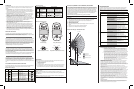
TROUBLESHOOTING
The following table provides corrective action for possible trouble situations. If further
assistance is required, please contact a Crestron customer service representative.
NOTE: Operation is ultimately determined by the control system program, and that must
be considered when troubleshooting.
B
ON
1
A
ON
1
B
ON
1
A
ON
1
B3
Lights do not turn ON
TROUBLE POSSIBLE CAUSE CORRECTIVE ACTION
Circuit breaker or fuse has
tripped.
Reset circuit breaker or
replace fuse.
Connections between
sensor and GLS-SIM (or
other interface device)
have been miswired.
Verify that all connections
have been made per the
wiring diagrams in this
document.
Lights stay ON
Constant motion.
To test, reduce red and
green knob by 15%; remove
motion source. If no
change, move sensor.
Infrared sensor can “see”
into hallway.
To test, put sensor in timer
Test mode and walk hallway. If
lights continue to come ON,
move sensor.
Lights remain ON too
long.
Timer setting too high. To test, check switch settings.
Typical setting is 10 minutes.
Incorrect programming in
control system.
Check control system logic or
contact Crestron for
assistance.
GLS-SIM (or other interface
device) set to incorrect Net
ID.
Check that the Net ID matches
the one expected by the control
system (or CLS-C6).
GLS-SIM DIP switch
settings not correct.
Refer to control system and
GLS-SIM documentation to
see if certain DIP switch
settings are required for
compatibility with this sensor.
Incorrect programming in
control system.
Check control system logic or
contact Crestron for
assistance.