


3
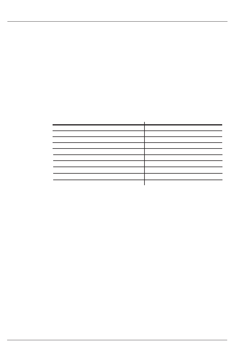
Flash Pattern Indication
Yellow on AC power present
Green on Charge complete
Green blinking Charging
Yellow & Green on simultaneously Charger in standby mode
Yellow & Green blink simultaneously No battery/reverse polarity
Yellow blinks 1X Not reaching constant voltage setpoint
Yellow blinks 2X Not reaching 24V within 2 hours
Yellow blinks 3X Charge current/voltage does not normalize
Yellow blinks 4X Battery voltage too high (over 32V)
Yellow blinks 5X Charger over temperature
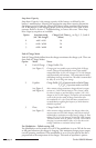
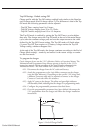
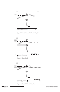
3. Restart: If the battery self-discharges below 12.9V for 12V batteries or below
25.7V for 24V batteries while the charger is in standby, the charger cycles into a
constant current of 1.0A (4A models)/2.0A (8A models) until the constant
voltage setpoint is reached. The unit will regulate and terminate as in Constant
Voltage Mode.
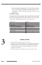
2.8 Indication Lights
The charger features built in diagnostics. Refer to the table below to interpret the
flashing of the yellow and green indicator lights. Flashing of the yellow indicator
means that the charging cycle has ended early and the battery may not be fully
charged. Refer to the Troubleshooting section to correct these faults.
INSTALLATION
• Charger should be securely mounted on a flat surface.
• The power cord to the IEC 320/C14 connector should be of the appropriate
gauge to carry a 10A current @ 120VAC, or a 5A current @ 230VAC for
the cable’s length, to meet the requirements of applicable electrical codes.
• A minimum of 30mm clearance should be provided at each end of the
charger for vented models.
• The charger should not be installed in locations which restrict air flow.
Curtis 1604/08 Manual
page 4