


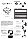
Method 2- Fixed Mounting
Step 1. Drill a hole that is
compatible with the
anchor and insert the
included anchor.
Step 2. Insert and tighten the
screw into the anchor.
Leave enough of the
screw exposed for the
sensor to be mounted to.
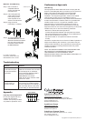
Step 3. Hang the sensor
horizontally or vertically.
Step 4. To connect the sensor
with RMCARD/PDU, use the
attached RJ45 Ethernet Cable.
Plug one end into the RJ45
Port and the other end into
the RMCARD/PDU.
HoleØ6mm(0.24in)
For further configuration
information, please refer to the
RMCARD/PDU user’s manual.
Universal RX/TXLink
RMCARD203
Conformance Approvals
FCC Warning
This equipment has been tested and found to comply with the
limits for a Class B digital device, pursuant to part 15 of the FCC
Rules. These limits are designed to provide reasonable
protection against harmful interference in a residential
installation. This equipment generates, uses and can radiate
radio frequency energy and, if not installed and used in
accordance with the instructions, may cause harmful interference
to radio communications. However, there is no guarantee that
interference will not occur in a particular installation. If this
equipment does not cause harmful interference to radio or
television reception, which can be determined by turning the
equipment off and on, the user is encouraged to try to correct the
interference by one or more of the following measures:
- Reorient or relocate the receiving antenna.
- Increase the separation between the equipment and receiver.
- Connect the equipment into an outlet on a circuit different from
that to which the receiver is connected.
- Consult the dealer or an experienced radio/TV technician
for help.
This device compiles with Part 15 of the FCC Rules. Operation is
subject to the following two conditions: (1) this device may not
cause harmful interference, and (2) this device must accept any
interference received, including interference that may cause
undesired operation.
NOTE: THE MANUFACTURER IS NOT RESPONSIBLE FOR
ANY RADIO OR TV INTERFERENCE CAUSED BY
UNAUTHORIZED TO THIS EQUIPMENT. SUCH
MODIFICATIONS COULD VOID THE USER’S AUTHORITY TO
OPERATE THE EQUIPMENT.
Troubleshooting
The RMCARD/PDU
is not able to acquire
environment sensor's
information.
Check the LED.
When the connection is ok, the LED
should always be on; otherwise,
ensure the RJ45 Ethernet cable is
correctly connected to the
RMCARD/PDU and sensor.
Note: Do not use a crossover cable
which is for Tx/Rx.
The Input Dry
Contact does not
function correctly.
Ensure the Input Dry Contact wires
are correctly connected and make
sure the open/short circuit setting of
the connected devices is the same
as the setting on the Web Interface.
Problem Solution
CyberPower North America
CyberPower Systems (USA), Inc.
Phone: (952)-403-9500 Toll-free: (877)297-6937
4241 12th Avenue E. Suite 400, Shakopee, MN 55379
E-mail: tech@cpsww.com
Website: www.CPSww.com
CyebrPower Europe
CyberPower Systems, Inc.
E-mail: sales@cpsww.eu
Website: www.cpsww.eu
CyberPower Systems France
Z.I. Saint Séverin 28220 CLOYES sur le Loir – France
Tél: +33(0)2 37 98 61 50
E-mail: sales@cpsww.com.fr
Copyright © 2011 CyberPower Systems, Inc.
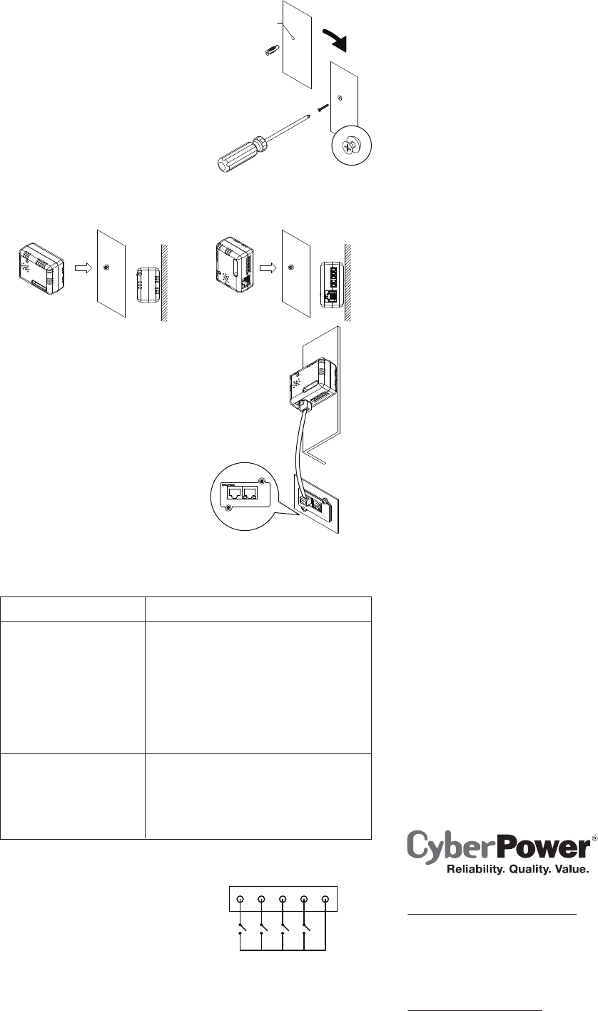
Dry Contact
External Sensor 1/2/3/4
COM
1 2 3 4
Appendix
Input Dry Contact Application
Do not input signals that carry
voltage into the input dry
contacts. The input dry contacts
only allow for open/short circuit.