


The compressor/limiter shall have four identical chan-
nels, each with an audio frequency response of 20Hz to
25kHz, +0/-0.5dB , an electronically floating balanced
input impedance of not less than 50kΩ, balanced and
20kΩ unbalanced, and a maximum input level of not less
than +22dBu and 1/4" TRS and XLR connectors. The
output shall have an impedance of no more than 30Ω
with a maximum output level of not less than +22dBm
balanced and +20dBm unbalanced, into a minimum load
impedance of 600Ω and 1/4” TRS and XLR type con-
nectors.
Total Harmonic Distortion plus Noise shall be less than
0.1% with any amount of compression (up to 40dB) at
1kHz and Intermodulation Distortion shall be less than
0.1% SMPTE. The unit shall have an Equivalent Input
Noise level of not more than -96dBu unweighted, and a
dynamic range of not less than 118dB. Output gain
adjustment shall be variable from -20 to +20dB. The
compression threshold range shall be variable from -40 to
+20dBu and compression ratio shall be variable from 1:1
to ∞:1. The peak limiter threshold range shall be variable
from 0 to +24dBu. The compressor attack and release
times shall be program dependent. The compression ratio
characteristic shall be selectable for either the hard or soft
knee curve type with a maximum compression of no less
than 60dB. All input and output signal connections shall
be via the rear panel. The channel-to-channel stereo links
shall be of the true RMS summing type. Channel 1 shall
link to Channel 2 and Channel 3 shall link to Channel 4
with channels 1 and 3 becoming the masters. The unit
shall have the following front panel switches for each
channel, with each switch incorporating an integral LED
to signal selection of that switch: OverEasy, I/O Meter,
and Bypass. There shall also be one Stereo Link switch
for each pair of channels. Each channel shall have the fol-
lowing identical controls: compression Threshold, com-
pression Ratio, compression Output Gain, limiter Threshold; and the following identical metering and indicator LEDs for each channel: Gain Reduction (8 LEDs), Input
or Output Level (8 LEDs), peak limiter active. There shall be a rear panel switch for each channel to select nominal input and output operating levels at -10dBV or +4
dBu. The unit shall be capable of accepting one compatible audio transformer installed for each channel. The power requirements shall be 100-120VAC 50/60Hz or 200-
240VAC, 50/60Hz, 20W, via a detachable IEC type AC cable. The size of the unit shall be 1.75" x 19" x 7.9" (4.4cm x 48.3cm x 20.1cm) with a net weight of 5.2 lbs
(2.4 kg) and a shipping weight of 7.6 lbs (3.5 kg). The 1U high, full rack width 4 channel compressor/limiter shall be a dbx 1046.
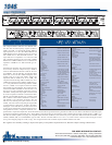
QUAD COMPRESSOR
1046
Input
Connectors: XLR and 1/4" TRS (Pin 2 and
tip hot)
Type: Electronically balanced/unbal-
anced, RF filtered
Impedance: Balanced > 40 kOhm, unbal-
anced >20 kOhm
Max Input Level: > +22 dBu balanced or unbal-
anced
CMRR: Typically >50 dB at 1 kHz
Output
Connectors: XLR and 1/4" TRS (Pin 2 and
tip hot)
Type: Servo-balanced/unbalanced,
RF filtered
Impedance: Balanced 30 Ohm, unbal-
anced 15 Ohm
Max Output Level: > +22 dBm balanced, > +20
dBm unbalanced
System Performance
Bandwidth: 20 Hz to 20 kHz, +0/-0.5 dB
Frequency Response: 0.35 Hz to 90 kHz, +0/-3 dB
Noise: < -96 dBu, unweighted, 22
kHz measurement bandwidth
Dynamic Range: > 118 dB, unweighted
THD+Noise: 0.008% typical at +4 dBu, 1
kHz unity gain
0.08% typical at +20 dBu, 1
kHz, unity gain
< 0.1% any amount of com-
pression up to 40 dB, 1 kHz
IMD: < 0.1% SMPTE
Interchannel Crosstalk: < -80 dB 20 Hz to 20 kHz
Stereo Coupling: True RMS Power Summing
Compressor
Threshold Range: -40 dBu to +20 dBu
Ratio: 1:1 to ∞:1
Threshold Characteristic: Selectable OverEasy® or
hard knee
Attack/Release Characteristic: AutoDynamic™
Attack Time: Program-dependent
Release Time: Program-dependent
Output Gain: -20 to +20 dB
Limiter
Threshold Range: 0 dBu to +24 dBu (off)
Ratio: ∞:1
Limiter Type: PeakStopPlus™ two-stage
limiter
Stage 1: PeakStop® brickwall limiter
Attack Time: Zero
Release Time: Zero
Stage 2: Predictive intelligent program
limiter
Attack Time: Program-dependent
Release Time: Program-dependent
Function Switches
OverEasy®: Activates the OverEasy®
compression function.
I/O Meter: Switches between monitoring
input and output levels
on the Input/Output Level meter.
Bypass: Activates the direct input-to-
output hard-wire bypass.
Operating Level
(rear panel): Switches the nominal operat-
ing level between -10 dBV
and +4 dBu simultaneously
for both input and output lev-
els.
ST Link: Links channels in stereo
pairs. Channels One
and Three become the mas-
ter channels.
Indicators
Gain Reduction Meter: 8 segment LED bar graph at
1, 3, 6, 10, 15, 20,
25, and 30 dB
Input/Ouptut Meter: 8-segment LED bar graph at
-24, -18, -12, -6, 0,
+6, +12, and +18 dBu
PeakStop®: 1 LED to indicate PeakStop®
limiting
Function Switches: LED indicator for each front-
panel switch
Options
Output Transformer
Per Channel: Jensen® JT-123-dbx or JT-
11-dbx, BCI™ RE-
123-dbx or RE-11-dbx
Power Supply
Operating Voltage: Switchable: 100-120 VAC 50-
60 Hz or 200-240 VAC 50/60
Hz
Power Consumption: 20 Watts
Fuse: 100-120 VAC:250 mA Slow
Blow
200-240 VAC: 125 mAType T
Mains Connection: IEC receptacle
Physical
Dimensions: 1.75"Hx19"Wx9"D
(4.4cmx48.3cmx20.1cm)
Weight: 5.2 lbs. (2.4 kg)
Shipping Weight: 7.6 lbs. (3.5 kg)
Note: Specifications subject to change.
LIMITERCOMPRESSOR
INPUT / OUTPUT LEVEL dBu THRESHOLDGAIN REDUCTION dB
LIMITERCOMPRESSOR LIMITERCOMPRESSOR LIMITERCOMPRESSOR
1046
Quad
Compressor/
Limiter
OverEasy I/O Meter Bypass
PROFESSIONAL PRODUCTS
OUTPUT GAIN
0
-20
-10
+10
+20
dB
RATIO
3:1
:1
8:1
4:1
1:1
1.5:1
2:1
OFF
+20
+14
+12
+4
+6
+10
dBu
THRESHOLD
-10
0
+20
+10
-40
-30
-20
dBu
INPUT / OUTPUT LEVEL dBu THRESHOLDGAIN REDUCTION dB
OverEasy I/O Meter Bypass
OUTPUT GAIN
0
-20
-10
+10
+20
dB
RATIO
3:1
:1
8:1
4:1
1:1
1.5:1
2:1
THRESHOLD
-10
0
+20
+10
-40
-30
-20
dBu
INPUT / OUTPUT LEVEL dBu THRESHOLDGAIN REDUCTION dB
OverEasy I/O Meter Bypass
OUTPUT GAIN
0
-20
-10
+10
+20
dB
RATIO
3:1
:1
8:1
4:1
1:1
1.5:1
2:1
THRESHOLD
-10
0
+20
+10
-40
-30
-20
dBu
INPUT / OUTPUT LEVEL dBu THRESHOLDGAIN REDUCTION dB
OverEasy I/O Meter Bypass
OUTPUT GAIN
0
-20
-10
+10
+20
dB
RATIO
3:1
:1
8:1
4:1
1:1
1.5:1
2:1
THRESHOLD
-10
0
+20
+10
-40
-30
-20
dBu
CHANNEL ONE CHANNEL TWO CHANNEL THREE CHANNEL FOUR
PeakStopPlus PeakStopPlus PeakStopPlus PeakStopPlus
Stereo
Couple
Stereo
Couple
-24 -18 -12 -6 0 +6 +12 +1830 25 20 15 10 6 3 1-24 -18 -12 -6 0 +6 +12 +1830 25 20 15 10 6 3 1-24 -18 -12 -6 0 +6 +12 +1830 25 20 15 10 6 3 1-24 -18 -12 -6 0 +6 +12 +1830 25 20 15 10 6 3 1
+ + + +
CHANNEL ONE
INPUTSOUTPUTS
OPERATING
LEVEL
+4 dBu
-10 dBV
CHANNEL TWO
INPUTSOUTPUTS
OPERATING
LEVEL
+4 dBu
-10 dBV
CHANNEL THREE
INPUTSOUTPUTS
OPERATING
LEVEL
+4 dBu
-10 dBV
CHANNEL FOUR
INPUTSOUTPUTS
OPERATING
LEVEL
+4 dBu
-10 dBV
OFF
+20
+14
+12
+4
+6
+10
dBu
OFF
+20
+14
+12
+4
+6
+10
dBu
OFF
+20
+14
+12
+4
+6
+10
dBu
PROFESSIONAL PRODUCTS
MANUFACTURED UNDER ONE OR MORE OF THE FOLLOWING U.S. PATENTS 4,234,804 4,316,107 4,329,598 4,331,931 4,377,792 4,403,199 4,409,500 4,425,551 4,434,380 4,454,433 4,471,324 4,473,793 OTHER PATENTS PENDING
®
A Harman International Company
FOR MORE INFORMATION CONTACT:
dbx Professional Products • 8760 S. Sandy Pkwy. • Sandy, Utah 84070
Phone (801) 568-7660 • Fax (801) 568-7662 • Int’l Fax (801) 568-7583
customer@dbxpro.com • http://www.dbxpro.com
dbx engineers are constantly working to improve the quality of our products. Specifications are, therefore subject to change without notice.