


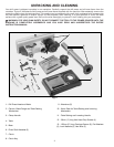


13
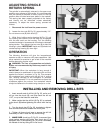
ADJUSTING SPINDLE
RETURN SPRING
The spindle is automatically returned to its upper most
position upon release of the handle. It is recommended
that the handle be allowed to slowly return to the top
position after all holes have been bored in the material.
This spring has been properly adjusted at the factory
and should not be disturbed unless absolutely
necessary. To adjust the return spring, proceed as
follows:
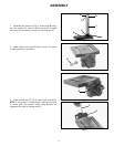
1. Disconnect the tool from the power source.
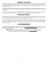
2. Loosen the two nuts (B) Fig. 32, approximately 1/4".
Do not remove nuts (B) from shaft (C).
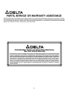
3. While firmly holding spring housing (A) Fig. 33, pull
out housing and rotate it until the boss (D) is engaged
with the next notch on the housing. Turn the housing
counterclockwise to increase and clockwise to decrease
spring tension. Then tighten the two nuts (B) to hold the
housing in place. IMPORTANT: Inside nut (B) should not
contact spring housing (A) when tight.
OPERATION
The following directions will give the inexperienced
operator a start on common drill press operations. Use
scrap material for practice to get a feel of the machine
before attempting regular work.
WARNING: The use of accessories and attach-
ments not recommended by Delta may result in risk
of injury.
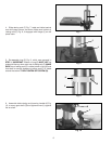
IMPORTANT: When the workpiece is long enough it
should always be positioned on the table with one end
against the column, as shown in Fig. 34. This prevents
the workpiece from rotating with the drill bit or cutting
tool, causing damage to the workpiece or personal
injury to the operator. If it is not possible to support the
workpiece against the column, the workpiece should
always be fastened to the table using clamps or a vise.
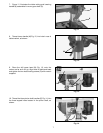
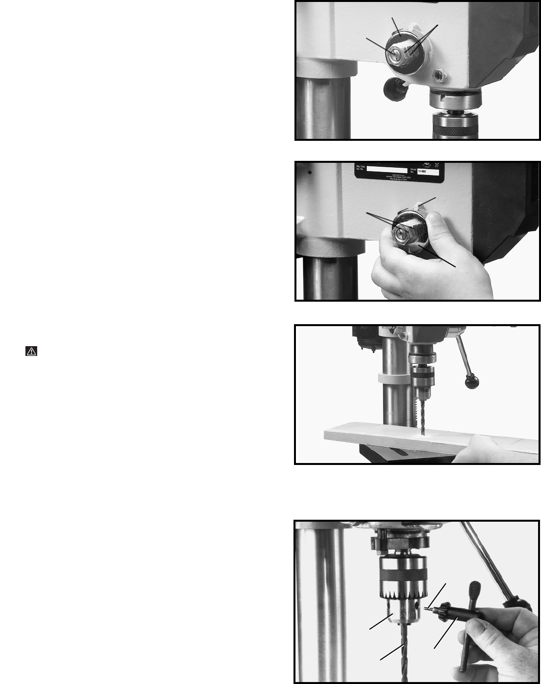
INSTALLING AND REMOVING DRILL BITS
1. Insert smooth end of drill bit (A) Fig. 35, as far as it
will go into the chuck (B), and then back the bit out
1/16", or up to the flutes for small bits.
2. Make certain that the drill bit (A) Fig. 35, is centered
in the chuck (B) before tightening the chuck with the key
(C).
3. Turn the chuck key (C) Fig. 35, clockwise to tighten
and counterclockwise to loosen the chuck jaws.
4. Tighten all three chuck jaws to secure the drill bit
sufficiently so that it does not slip while drilling.
5. MAKE SURE chuck key (C) Fig. 35, is removed from
chuck before starting drill press. Your chuck key (C) is
equipped with a self-ejecting pin (D) which eliminates
the hazard of the key being left in the chuck.
Fig. 32
Fig. 33
Fig. 34
B
C
A
D
A
B
Fig. 35
C
D
B
A