


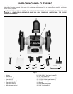
5
ASSEMBLY
TOOL RESTS
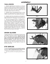
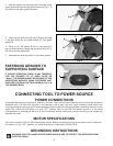
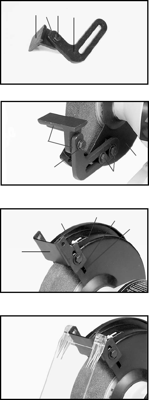
1. Assemble adjustable tool rest (A) Fig. 3, to left side
of tool rest arm (B), as shown, and fasten with one 5/16-
18x3/4" hex head screw (C) and 5/16" lockwasher (D).
Assemble the remaining tool rest to the right side of the
other tool rest arm in the same manner. Do not
completely tighten hardware at this time.
2. Assemble left tool rest assembly (D) Fig. 4, to the
inside of left wheel guard (E), and fasten with two 5/16-
18x5/8" screws (F) and 3/4" flat washers (G) as shown.
3. Assemble right tool rest assembly to the inside of
right wheel guard and fasten with two 5/16-18x5/8" hex
head screws and 3/4" flat washers in the same manner.
4. Each tool rest assembly (D) Fig. 4, is adjustable so it
can be positioned slightly below the centerline of the
wheel and as close to the grinding wheel as possible,
giving maximum support to the piece that is being
ground. Always maintain a distance of 1/8" or less
between the grinding wheel and the inside edge of the
tool rest. As the wheels wear down, the tool rest should
be adjusted accordingly. When the tool rest is positioned
correctly, tighten hardware (C) and (F). Freehand
grinding without the use of a tool rest should always be
done on the lower quarter of the wheel.
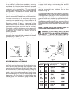
SPARK GUARDS
The spark guard (A) Fig. 5, is mounted to the side of each
wheel guard, using the 1/4-20x1/4" hex head screw (B)
and 1/4" flat washer (C) as shown. NOTE: The tab (D)
Fig. 5, on the side of the spark guard (A), must be
placed in slot (E), before attaching the spark guard
(A) to the grinder. The spark guard (A) should be
adjusted as close as possible to the grinding wheel so
that sparks never strike the operator’s hand. As the
wheels wear down, the spark guard (A) should be
adjusted accordingly.
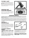
EYE SHIELDS
Your grinder is supplied with two eye shields for operator
protection. NOTE: ALWAYS WEAR EYE PROTECTION.
To assemble the eye shields, proceed as follows:
1. Place the eye shield on the spark guard as shown in
Fig. 6.
Fig. 3
Fig. 4
Fig. 5
Fig. 6
A
C
B
D
C
G
F
E
C
A
B
D
E
D