


6
Fig. 3
ASSEMBLY
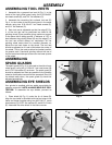
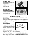
ASSEMBLING TOOL RESTS
1. Assemble the v-grooved tool rest (A) Fig. 3, to the
inside of the right wheel guard using two 5/16-18x5/8"
hex head screws (B), and 3/4" flat washers (C).
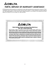
2. Assemble the remaining flat surfaced tool rest (D)
Fig. 4, to the inside of the left wheel guard in the same
manner using two 5/16-18x1/2" hex head screws (E),
and 3/4" flat washers (C).
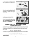
3. Each tool rest is adjustable so that the edge (F) Fig.
4, of the tool rest can be positioned as close to the
grinding wheel (G) as possible giving maximum support
to the piece that is being ground. A distance of 1/8" or
less between the grinding wheel (G) and the edge (F) of
the tool rest should always be maintained. As the
grinding wheel wears down to a smaller diameter, re-
adjust the tool rest closer to the wheel. The tool rest
should be adjusted so it is set a little below the center of
the wheel. This is the most practical and safest position
for general work. Free-hand grinding without the use of
the tool rest should always be done on the lower quarter
of the wheel.
Fig. 4
ASSEMBLING
SPARK GUARDS
The spark guard (A) Fig. 5, is mounted to the side of each
wheel guard, using the 1/4-20x1/4" hex head screw (B)
and 11/16" flat washer (C) as shown. The spark guard (A)
should be adjusted as close as possible to the grinding
wheel so that sparks never strike the operator’s hand. As
the wheels wear down, the spark guard (A) should be
adjusted accordingly.
Fig. 6
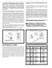
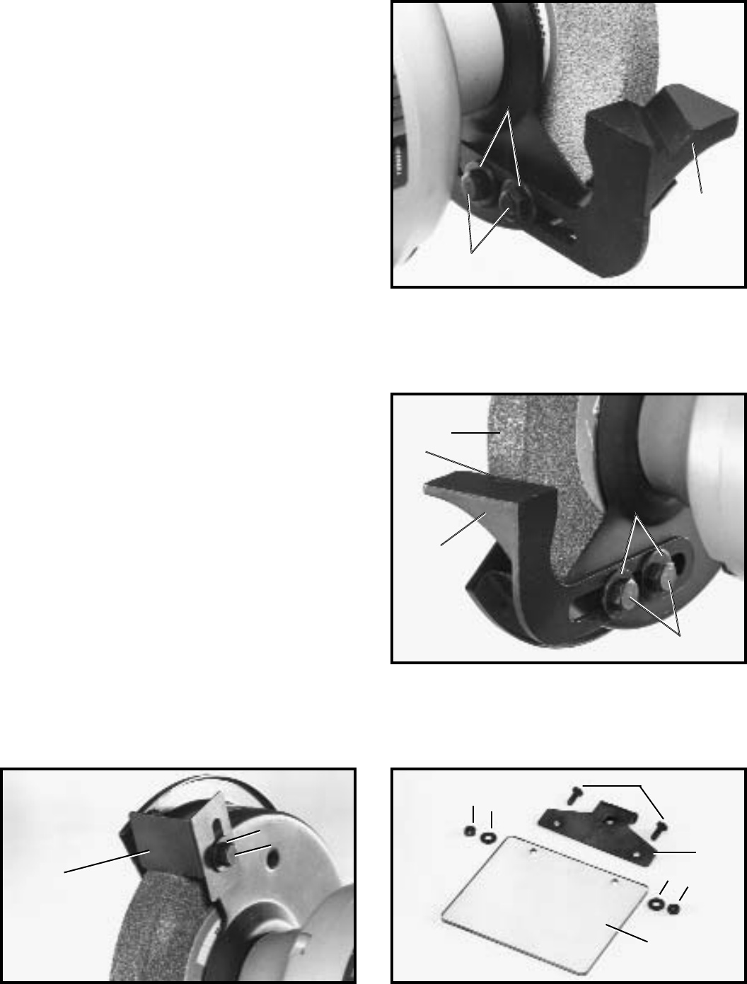
ASSEMBLING EYE SHIELDS
Your grinder is supplied with two safety eye shields for
operator protection. NOTE: ALWAYS WEAR EYE PRO-
TECTION. To assemble the eye shields, proceed as
follows:
1. Place shield (A) Fig. 6, under the lip of frame (B).
Align the two holes in the shield with the two holes in the
frame and fasten together using two #10-24x1/2" round
head screws (C),15/32" flat washers (D), and #10-24 nuts
(E). Assemble the other shield in the same manner.
Fig. 5
A
B
C
G
F
D
C
E
A
B
C
B
D
E
A
E
D
C