


6
ASSEMBLY
Fig. 3
Fig. 4
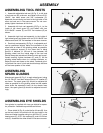
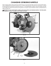
ASSEMBLING TOOL RESTS
1. Assemble adjustable tool rest (A) Fig. 3, to left side
of tool rest arm (B), as shown, and fasten with one 5/16-
18x3/4" hex head screw and 3/8" lockwasher (C).
Assemble the remaining tool rest to the right side of the
other tool rest arm in the same manner. Do not com-
pletely tighten hardware at this time.
2. Assemble left tool rest assembly (D) Fig. 4, to the
inside of left wheel guard (E), and fasten with two
5/16-18x5/8" screws (F) and 3/8" flat washers (G) as
shown.
3. Assemble right tool rest assembly to the inside of
right wheel guard and fasten with two 5/16-18x5/8" hex
head screws and 3/8" flat washers in the same manner.
4. Each tool rest assembly (D) Fig. 4, is adjustable so it
can be positioned slightly below the centerline of the
wheel and as close to the grinding wheel as possible,
giving maximum support to the piece that is being
ground. A distance of 1/8-inch or less between the
grinding wheel and the inside edge of the tool rest
should always be maintained. When the tool rest is posi-
tioned correctly, tighten hardware (C) and (F). As the
grinding wheel wears down to a smaller diameter, re-
adjust the tool rest closer to the wheel. Freehand grind-
ing without the use of a tool rest should always be done
on the lower quarter of the wheel.
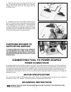
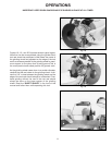
ASSEMBLING
SPARK GUARDS
Attach spark guard (A) Fig. 5, to each wheel guard, using
the 1/4-20x1/4" hex head screw (B) and 1/4" washer (C)
as shown. The spark guard (A) should be adjusted as
close as possible to the grinding wheel so that sparks
never strike the operator’s hand. As the wheels wear
down, the spark guard (A) should be adjusted accord-
ingly.
ASSEMBLING EYE SHIELDS
Your grinder is supplied with two eye shields for opera-
tor protection. Assemble eye shields as follows:
1. Place shield (A) Fig. 6, under the lip of frame (B). Line
up the two holes in the shield with the two holes in the
frame and fasten together using two #10-24x1/2" round
head screws (C), 3/16" flat washers (D), and #10-24 hex
nuts (E). Assemble the other shield in the same manner.
A
C
B
E
F
C
D
Fig. 5
Fig. 6
A
C
B
C
B
D
A
D
E
E
G