


9
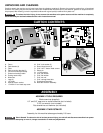
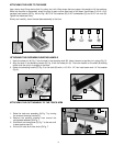
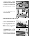
Use a heavy-duty lifting device (fork lift, pulley, etc.) with lifting straps that can support the weight to lift the machine.
While the machine is suspended, attach the legs to each corner (see inset) of the base. Use sixteen 5/16-18 x 5/8"
carriage head screws (A) Fig. 4A and Fig. 4B, 5/16" flat washers (B), 5/16" lockwashers (C) and 5/16" hex nuts (D).
Tighten the hardware firmly.
Slowly and carefully, lower the saw/base assembly to the floor.
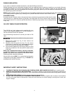
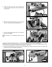
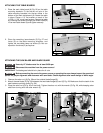
1. Insert the shear pin (A) Fig. 5 into the hole in the elevating shaft (B). Use a hammer to tap this pin in place (Fig. 5).
2. Align the slots in the elevating handle (C) Fig. 5 with the shear pin (A). Place the handle on the shaft (B) making
certain that the roll pin is engage in the slots.
3. Fasten the elevating handle (C) Fig. 5 to the shaft (B) with a 1/4"-20 x 1/2" hex head screw and 1/4" flat washer
(Fig. 6).
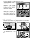
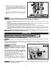
1. Raise the track arm assembly (A) Fig. 7 by turning
the overarm elevating handle (D).
2. Remove the packing material from around the
cuttinghead assembly (B) Fig. 7.
3. Push track arm clamp lever (C) Fig. 7 to the rear until
it rests against stop (D).
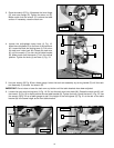
4. Pull out on track arm index knob (E) Fig. 7.
ATTACHING THE LEGS TO THE BASE
ATTACHING THE OVERARM ELEVATING HANDLE
Fig. 4B
Fig. 5
Fig. 6
A
B C D
C
A
B
ATTACHING THE CUTTINGHEAD TO THE TRACK ARM
A
D
F
E
B
C
Fig.7
Fig. 4A
D