


7
CONNECTING SCROLL SAW TO POWER SOURCE
POWER CONNECTIONS
A separate electrical circuit should be used for your tools. This circuit should not be less than #12 wire and should be
protected with a 20 Amp fuse. Have a certified electrician replace or repair a worn cord immediately. Before connect-
ing the motor to a power line, make sure the switch is in the "OFF" position and be sure that the electric current is of
the same characteristics as stamped on the motor name-plate. Running on low voltage will damage the motor.
WARNING: DO NOT EXPOSE THE TOOL TO RAIN OR OPERATE THE TOOL IN DAMP LOCATIONS.
MOTOR SPECIFICATIONS
Your scroll saw is wired for 110-120 volt, 60 HZ current. Before connecting the saw to the power source, make sure
the switch is in the "OFF" position.
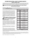
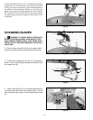
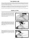
EXTENSION CORDS
Use proper extension cords. Make sure your extension
cord is in good condition and is a 3-wire extension cord
which has a 3-prong grounding type plug and a 3-pole
receptacle which will accept the tools plug. When using
an extension cord, be sure to use one heavy enough to
carry the current of the scroll saw. An undersized cord
will cause a drop in line voltage, resulting in loss and
overheating. Fig. 14 shows the correct gage to use
depending on the cord length. If in doubt, use the next
heavier gage. The smaller the gage number, the heavier
the cord.
GROUNDING INSTRUCTIONS
WARNING: THIS TOOL MUST BE GROUNDED
WHILE IN USE TO PROTECT THE OPERATOR
FROM ELECTRIC SHOCK.
In the event of a malfunction or breakdown, grounding
provides a path of least resistance for electric current to
reduce the risk of electric shock. This tool is equipped
with an electric cord having an equipment-grounding
conductor and a grounding plug. The plug must be
plugged into a matching outlet that is properly installed
and grounded in accordance with all local codes and
ordinances.
Do not modify the plug provided - if it will not fit the out-
let, have the proper outlet installed by a qualified electri-
cian.
Improper connection of the equipment-grounding con-
ductor can result in risk of electric shock. The conductor
with insulation having an outer surface that is green with
or without yellow stripes is the equipment-grounding
0-6
0-6
0-6
0-6
120
120
120
120
up to 25
25-50
50-100
100-150
18 AWG
16 AWG
16 AWG
14 AWG
Ampere
Rating
Volts
Total Length of
Cord in Feet
Gage of
Extension Cord
6-10
6-10
6-10
6-10
120
120
120
120
up to 25
25-50
50-100
100-150
18 AWG
16 AWG
14 AWG
12 AWG
10-12
10-12
10-12
10-12
120
120
120
120
up to 25
25-50
50-100
100-150
16 AWG
16 AWG
14 AWG
12 AWG
12-16
12-16
12-16
120
120
120
up to 25
25-50
14 AWG
12 AWG
GREATER THAN 50’ NOT RECOMMENDED
0-6
0-6
0-6
0-6
6-10
6-10
6-10
6-10
10-12
10-12
10-12
10-12
12-16
12-16
12-16
240
240
240
240
240
240
240
240
240
240
240
240
240
240
240
up to 50
50-100
100-200
200-300
up to 50
50-100
100-200
200-300
up to 50
50-100
100-200
200-300
up to 50
50-100
18 AWG
16 AWG
16 AWG
14 AWG
18 AWG
16 AWG
14 AWG
12 AWG
16 AWG
16 AWG
14 AWG
12 AWG
14 AWG
12 AWG
GREATER THAN 100’ NOT RECOMMENDED
MINIMUM GAUGE EXTENSION CORD
conductor. If repair or replacement of the electric cord or plug is necessary, do not connect the equipment grounding
conductor to a live terminal.
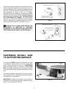
Check with a qualified electrician or service personnel if the grounding instructions are not completely understood, or
if in doubt as to whether the tool is properly grounded.Use only 3-wire extension cords that have 3-prong grounding
type plugs and 3-hole receptacles that accept the tool's plug, as shown in Fig. 15.
Repair or replace damaged or worn cord immediately.
Fig. 14