4
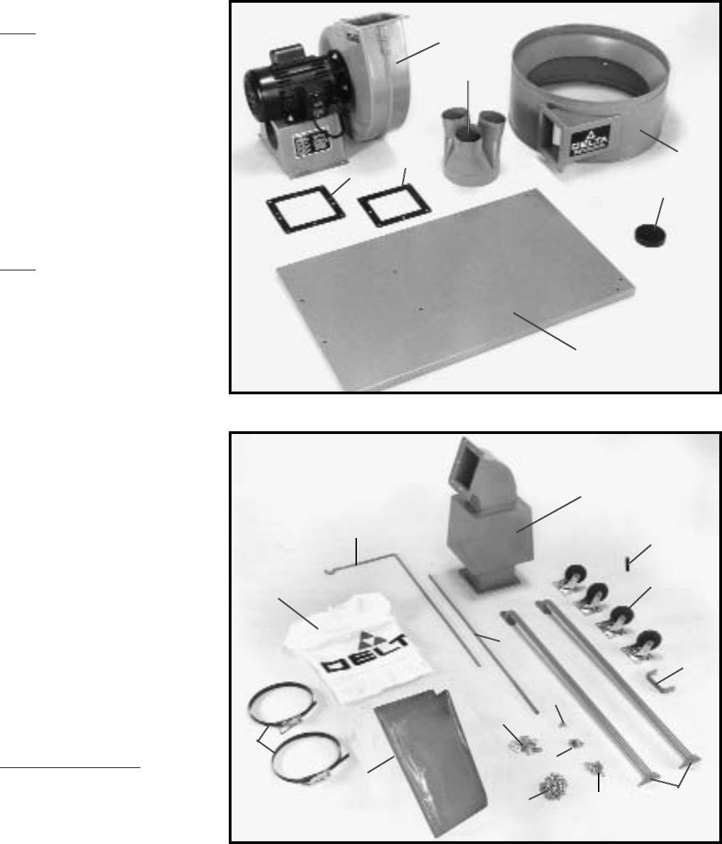
Fig. 2
Fig. 3
Fig. 2
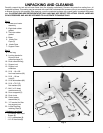
1 - Blower and motor
assembly
2 - Eight-hole rubber
gasket
3 - Ten-hole rubber
gasket
4 - Base
5 - Intake Port
Caps (3)
6 - Intake Ports
7 - Support Drum
Fig. 3
8 - Filter bag
9 - Locking bands for
filter and dust
collection bags (2)
10 - Dust collection bag
11 - Support rod
12 - Support rod
extension
13 - 5/16 - 18 x 5/8
hex head screws (48)
14 - 5/16 - 18 hex
nuts (6)
15 - 5/16 lockwashers (48)
16 - 5/16 x 7/8 O.D.
flat washers (26)
17 - M4.2 x 12 sheet
metal screws (4)
18 - Drum supports (2)
19 - Dust chute
20 - Swivel caster
assemblies (4)
21 - “U” bracket for filter
bag support rod
22 - Lower Dust Bag
retaining Clips (4)
* Har
dware not shown
* -1/4-20x5/8" Hex Head
Screws (8)
* -1/4" Lockwashers (8)
* -1/4"-20 Hex Nuts (8)
1
2
3
4
5
6
7
8
9
10
11
12
13
14
15
16
17
18
19
20
21
UNPACKING AND CLEANING
Carefully unpack the tool and all loose items from the shipping container(s). Remove the protective coating from all
unpainted surfaces. This coating may be removed with a soft cloth moistened with kerosene (do not use acetone, gasoline
or lacquer thinner for this purpose). After cleaning, cover the unpainted surfaces with a good quality household floor paste
wax. ILLUSTRATIONS ARE REPRESENTATIVE ONLY AND MAY NOT DEPICT THE ACTUAL COLOR, LABELING
OR ACCESSORIES AND MAY BE INTENDED TO ILLUSTRATE TECHNIQUE ONLY
22


