10 - English
FLEXIBLE LAMP
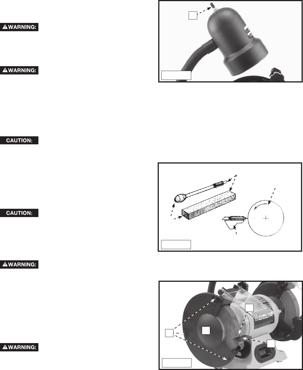
The flexible lamp op er ates in de pen dent ly of the grinder.
To turn the lamp on and off, rotate switch (A) Fig. 10.
To reduce the risk of fire, use 40 watt
or less, 120 volt, reflector track type light bulb (not
supplied). A stan dard house hold light bulb should not
be used. The reflector track type light bulb should not
extend below the lamp shade.
GRINDING WHEELS
The use of accessories and
attachments not recommended by Delta may result
in risk of injuries. Grinding wheels used with this
grinder should be rated for 3600 RPM or higher and
be 6" (152 mm) in diameter with a 1/2" (12.7 mm) arbor hole.
Two aluminum oxide grinding wheels are supplied with your grinder; one 36 grit and one 60 grit. For best grinding results,
and to maintain good balance, always keep the wheels properly dressed. Do not force the work against a cold wheel.
The grinding wheel should always be run at idle speed for one full minute before applying work. It is recommended that
only balanced wheels be used with your grinder. The use of balanced wheels adds years to the life of the bearings on the
grinder and by eliminating the most common source of vibration, more accurate work is accomplished.
ALWAYS maintain a distance of 1/8" (3.2 mm) or less between the grinding wheel and the tool
rest. Adjust the tool rests and spark guards as the grinding wheels decrease in size with use.
DRESSING A GRINDING WHEEL
When dressing a grinding wheel use a suitable silicon (A)
carbide stick type dresser (B), as shown in Fig. 11. Move
the dresser forward on the tool rest (D) until it touches
the high point on the face of the wheel (C). Dress the
wheel by moving the dresser back and forth. Repeat this
operation until the face of the grinding wheel is clean and
the corners of the wheels are square.
ALWAYS maintain a distance of 1/8"
or less between the grinding wheel and the tool
rest. Adjust the tool rests and spark guards as the
grinding wheels decrease in size with use.
CHANGING THE GRINDING WHEELS
Disconnect machine from power source!
1. Remove the screws (A) Fig. 12 and the side covers (B) from the grinding wheel.
2. To prevent shaft rotation, place a wedge between the
grinding wheel (C) and the tool rest (D).
NOTE: To remove the left grinding wheel, turn the arbor
nut clockwise (toward the front) to loosen. To remove the
right grinding wheel, turn the arbor nut counter-clockwise
(toward the front) to loosen.
3. If the replacement wheel does not require the arbor
bushing, save it for future use.
4. To install a new wheel, reverse the procedure.
Do not overtighten the wheel nuts
when installing grinding wheels. Tighten the wheel nuts
enough to drive the wheel and prevent slippage.
A
Fig. 10
Fig. 12
A
B
D
C
A
C
D
Fig. 11
B


