13
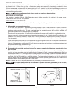
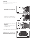
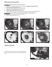
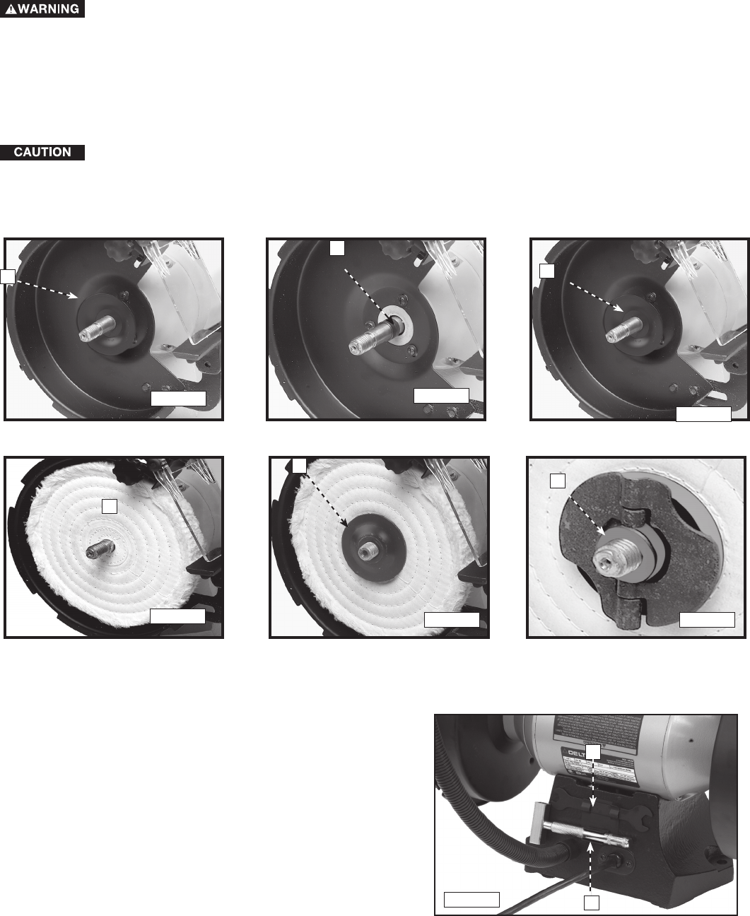
1. Remove one grinding wheel as instructed in the section “CHANGING GRINDING WHEELS.”
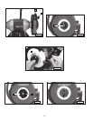
2. Remove the inner wheel flange (A) Fig. 16.
3. Place the buffing wheel bushing (B) Fig. 17 on the shaft.
4. Replace the inner wheel flange (C) Fig. 18 on the shaft.
5. Place the buffing wheel (D) Fig. 19 on the shaft.
6. Place the other wheel flange (E) Fig. 20 on the shaft.
7. Thread the arbor nut (F) Fig. 21 on the arbor until the arbor nut makes contact with the arbor flange.
8. Push the arbor nut wings out to the closed position, flat against the arbor flange (Fig. 21).
The arbor nut wings must contact the arbor flange to prevent vibration.
9. Replace the wheel cover that was removed in STEP 2.
10. Adjust the spark guard and tool rest.
INSTALLING BUFFING WHEEL
A
B
C
D
E
F
Disconnect machine from power source.
Fig. 16
Fig. 17
Fig. 19
Fig. 18
Fig. 21
Fig. 20
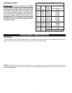
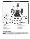
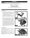
Store the open end wrench (A) and the wheel dressing
wrench (B) in the holder at the rear of the grinder (Fig.
22.)
WRENCH STORAGE
A
B
Fig. 22


