


SB-2-628-K PAGE 5
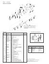
PARTS REPLACEMENT
Tools Required:
Crescent Wrench or "C" Spanner
1/2" Box Wrench or 1/2" Socket Spanner (Ref. 3)
9/16" Open Wrench (Ref. 9) or 9/16" spanner
Long Neck Vise Grip Pliers (19) or long nose grips
Hex Wrench 1/8" for (Ref. 24)
Hex Wrench 3/16" for (Ref. 7)
Fluid needle (28) , Tip (3) and Needle Packings (11)
1. Relieve all air and fluid pressure in the system.
2. Remove retaining ring (1) & air cap (2).
3. Remove fluid tip (3).
To avoid serious gun damage, do not remove the fluid
tip (nozzle) (3) from the spray gun (spray piston) when
the fluid inlet adaper (6 or 9) is removed. Doing so may
allow the stainless steel insert to break free from the
aluminum body, which is non-repairable.
4. It is recommended that both the fluid tip (nozzle) (3) and the
needle (28) be replaced at the same time. The needle packings
(11) should also be replaced when replacing the needle.
5. Remove adjusting knob (25).
6. Remove needle (28) with pliers.
7. Loosen four screws (7) and remove sprayhead (8).
8. With the sprayhead (8) removed, the packings (11) can be easily
removed and replaced.
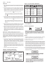
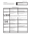
9. Slide onto the new needle (28), in this order, 1 packing (11),
spring (12) and 1 packing (11). Be sure to orient the packings as
shown (Figure 4).
10. Assemble sprayhead (8) with retaining screws (7).
11. Tighten screws (7) with a 3/16 hexagon key 30-40 in. lbs.
(3.4 - 4.5 N-m) until the body is flush with sprayhead assembly.
12. Reassemble in reverse order.
Piston (19) , O-Rings (17 & 18) and Air Packing (20)
1. Remove the back piece (29) by removing the rear retaining
screws (7).
2. Remove fluid needle (28).
3. Remove springs (30, 31 & 27) and piston (19). Care must be
taken when removing the piston (19). Use a locking long nose
vice grip pliers to extract the piston by clamping on the inner
ring on the back of the piston.
4. Remove the air packing (20), "O" rings (17 & 18).
5. Wipe clean the bore of the cylinder. Replace the piston "O" rings
(17 & 18) and lightly lubricate with clean petroleum jelly. See
"LUBRICATION" section which follows.
6. To replace air packing (20) (inside of the piston), slide packing
(20) over the needle (28) with the lead-in chamfer towards the
fluid tip (nozzle) end of the needle. Insert the needle into the
piston (19). Hold the piston in your hand so that the tip end of
the needle is protruding downward (protect the needle from
damage). Lightly tap the blunt end of the needle to drive the
packing down into the piston. The needle will stop inside the
piston at a shoulder.
7. Fit complete assembly into gun.
8. Lubricate the outside of springs (31) and (27) (see "LUBRICA-
TION" section), then re-install springs and back piece (29) and
tighten down and torque mounting screws (7) 30-40 in. lbs. (3.4
to 4.5 N-m).
9. Lubricate the adjustment knob threads (25) after cleaning with
•SSL-10 Gun Lube. Loosen the locking nut (26) before screwing
the adjustment knob in.
•Material Safety Data Sheet available from DeVilbiss upon request.
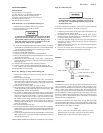
Plug (6) or Fluid Insert (9)
Halogenated Hydrocarbon solvents can chemically re-
act with aluminum. A risk of explosion or severe corro-
sion will occur. The following assembly step must be
carefully performed.
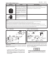
If replacing AGX-415 inlet fitting, or if it should loosen, follow the
assembly procedures below, and refer to Figure 3.
1. If installing a used fitting, clean paint and thread sealant from
the fitting threads and gun body.
2. Screw the jam nut all the way onto the fitting. Then apply a
medium strength thread sealant (i.e. Loctite 242 blue, or equal)
to the first few threads of the fitting.
3. Install the AGX-415 fitting into the spray gun and tighten to a
maximum of 12 ft. lbs. (16.3 N-m) torque. (Do not overtighten,
damage may occur.)
4. Tighten the jam nut to 16 ft. lbs. (21.7 N-m) torque using a thin
9/16" open end wrench.
5. Use two wrenches when removing a hose connection from
AGX-415 to prevent the inlet fitting from loosening.
LUBRICATION
The piston O-rings (17 and 18) must be lubricated when the piston
(19) is removed. Lightly lubricate with clean petroleum jelly.
Petroleum jelly is effective as a lubricant up to approximately 110°F
(43°C). Above 110°F (43°C), petroleum jelly will become "liquid"
and will not lubricate the O-rings adequately. If the ambient tem-
perature adjacent to the spray gun exceeds 110°F (43°C), use Parker
O-Lube or suitable high temperature grease. This allows the spray
gun to be used in temperatures up to 150°F (65° C) continous
without lubrication degradation.
Lubricate the outside of the larger piston spring (30) and needle
spring (27) with a light coating of non-silicone grease. Apply a thin
film of petroleum jelly (petroleum based grease) to the fluid needle
(28) as shown in the "Note" on Page 6.
Note
Due to close part tolerances, after repairing the gun,
actuate the gun on and off 7 or 8 times to "break-in" the air
packing (20). Do this with the material supply off.
FIGURE 3
Clean threads
16 ft. lbs. torque
12 ft. lbs. torque
Do not overtighten.
Loctite 242, blue or equal