


Page 4 SB-2-540
INSTALLATION
Important: To ensure that this
equipment reaches you in first
class condition, protective
coatings have been used. Flush
the equipment through with a
suitable solvent before use.
1. Attach air hose to connector (13).
Recommended hose size 8 mm
bore. The hose must be conductive
and electrical bond from the
spraygun to earth should be checked
with an ohmeter. A resistance of less
than 10
6
Ohms is recommended.
2. Air supply should be filtered and
regulated.
3. Attach Cup assembly (22) by
screwing into the Fluid Inlet of the
spraygun. Tighten with a wrench.
OPERATION
1. Mix coating material to manufac-
turers instructions.
2. Fill the cup with the required amount
of material. Fill to no more than
25mm (1") from the top of the cup.
DO NOT OVERFILL.
3. Attach Cup Lid.
4. Turn needle adjusting screw (7)
clockwise to prevent movement.
5. Turn spreader valve (5) counter-
clockwise to fully open.
6. Adjust inlet air pressure (For recom-
mended figures see Specifications)
at the gun inlet with the gun trig-
gered. (pressure gauge attachment
shown under Accessories is recom-
mended for this).
7. Turn needle adjusting screw counter
clockwise until first thread shows.
8. Test spray. If the finish is too dry
reduce airflow by reducing air inlet
pressure or by the optional Airflow
Valve (14). Screw the Adjusting
Knob (14) in to reduce pressure.
9. If finish is too wet reduce fluid flow
by turning needle screw (7) clock-
wise. If atomization is too coarse,
increase inlet air pressure. If too fine
reduce inlet pressure.
10. The pattern size can be reduced by
turning adjusting valve (5) clock-
wise.
11. Hold gun perpendicular to surface
being sprayed. Arcing or tilting may
result in uneven coating.
12. The recommended spray distance is
150-200 mm (6"-8").
13. Spray edges first. Overlap each
stroke a minimum of 50%. Move gun
at a constant speed.
14. Always turn off air supply and
relieve pressure when gun is not in
use.
PREVENTATIVE MAINTENANCE
1. Turn off air and relieve pressure in
the supply lines, or if using QD
system, disconnect from airline.
2. Remove Cup Lid (20) and empty
coating material into a suitable
container. Clean the gun and cup,
preferably in a gun wash machine.
Clean the cup.
3. Check the breather hole in the Lid
and the Drip Check Lid is not
blocked.
4. Remove air cap (1) and clean. If any
of the holes in the cap are blocked
with coating material use a toothpick
to clean. Never use metal wire which
could damage the cap and produce
distorted spray patterns
5. Ensure the tip of the nozzle (2) is
clean and free from damage. Build
up of dried paint can distort the
spray pattern.
6. Lubrication – stud/screw (6), needle
(9) and air valve (11) should be oiled
each day.
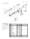
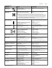
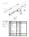
REPLACEMENT OF PARTS
Nozzle (2) and Needle (9) – Remove parts
in the following order: 7, 8, 9, 1 and 2.
Replace any worn or damaged parts and
re-assemble in reverse order.
Recommended tightening torque for
nozzle (2) 9.5-12 Nm (80-100 lbf in).
Packing – Remove parts 7, 8, 9. Unscrew
cartridge (4). Fit new cartridge finger
tight. Re-assemble parts 9, 8, and 7 and
tighten cartridge (4) with spanner suffi-
cient to seal but to allow free movement
of needle. Lubricate with gun oil.
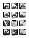
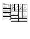
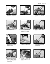
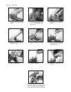
Air Valve Seal Kit (16) – (Refer to photos
1 to 28 and fig 2)
Spreader valve (5) – Caution: always
ensure that the valve is in the fully open
position by turning screw fully counter-
clockwise before fitting to body.
SPECIFICATION
Air supply connection:
Universal 1/4" BSP and NPS
Maximum static Air inlet pressure:
P
1
= 12 bar (175 psi)
Nominal gun Air inlet pressure
with gun triggered:
2 bar (29 psi) 510 Trans-Tech Air Cap
Maximum Service temperature: 40°C
Gun Weight: 412 g
MATERIALS OF CONSTRUCTION
Gun body: Anodized Aluminum
Nozzle: Stainless Steel
Needle: Stainless Steel
Fluid Inlet / Fluid Passages:
Anodized Aluminum
Trigger: Nickel Plated Steel