


11
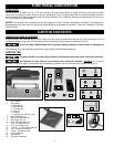
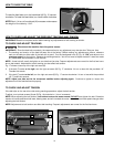
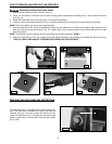
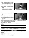
HOW TO SET THE HEIGHT SCALE
1. Run a piece of lumber through the drum sander (Fig. 22) to finish one side of the board.
2. Use a square (A) Fig. 23 to measure the thickness of the lumber.
3. Loosen the bolt (B) Fig. 24. Move scale up or down until the cursor shows the exact board thickness that was measured
in STEP 2. Tighten the bolt.
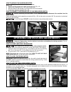
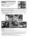
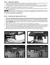
1. To check, sand a wide board (B) Fig. 19 (preferably 12" or more in width x 2 feet
long) until it is flat across the total surface area on both sides.
A. To do a quick check, draw pencil lines (C) Fig. 20 extending across the
width of the board at several places along the length of the board. DO NOT
ADJUST THE TABLE HEIGHT.
B. Reverse the board (end for end) and run it through the sander. If the sanding
table is set properly, the drawn lines will disappear. If the lines still appear on
the left or right side of the board, adjust the table height.
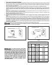
2. Use a 1/2" wrench to hold the leveling bolts (one shown at (E) Fig. 21). Use a
3/16" hex wrench (D) to loosen the hex bolts. Rotate the leveling bolts one flat
at a time until the table is parallel to the drum.
NOTE: A turn of one flat on the leveling bolt will raise or lower the table .010". Turn
the leveling bolt (E) Fig. 20 clockwise to lower the table or counter-clockwise to raise
the table. Adjust both leveling bolts the same amount and in the same direction.
3. Tighten the bolts loosened in STEP 2.
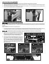
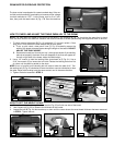
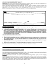
HOW TO CHECK AND ADJUST THE TABLE PARALLEL TO THE DRUM
NOTE: The table was set parallel to the drum at the factory. The distance (B) Fig. 18 should be the same front to back
over the entire width of the feed belt. Measure the board thickness at several places along the length and width to be sure.
Fig. 18
Fig. 21
Fig. 20
Fig. 19
Fig. 22
Fig. 23
Fig. 24
B
B
B
C
A
E
D
B
B
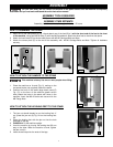
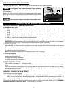
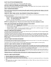
The drum motor is equipped with a reset overload relay. If the mo-
tor fails to start because of overloading or because of low voltage,
turn both switches to "OFF". Let the motor cool for 3 to 5 min-
utes, then push the reset button (A) Fig. 17B. Start the machine.
Fig. 17B
DRUM MOTOR OVERLOAD PROTECTION
A