11
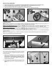
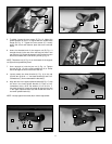
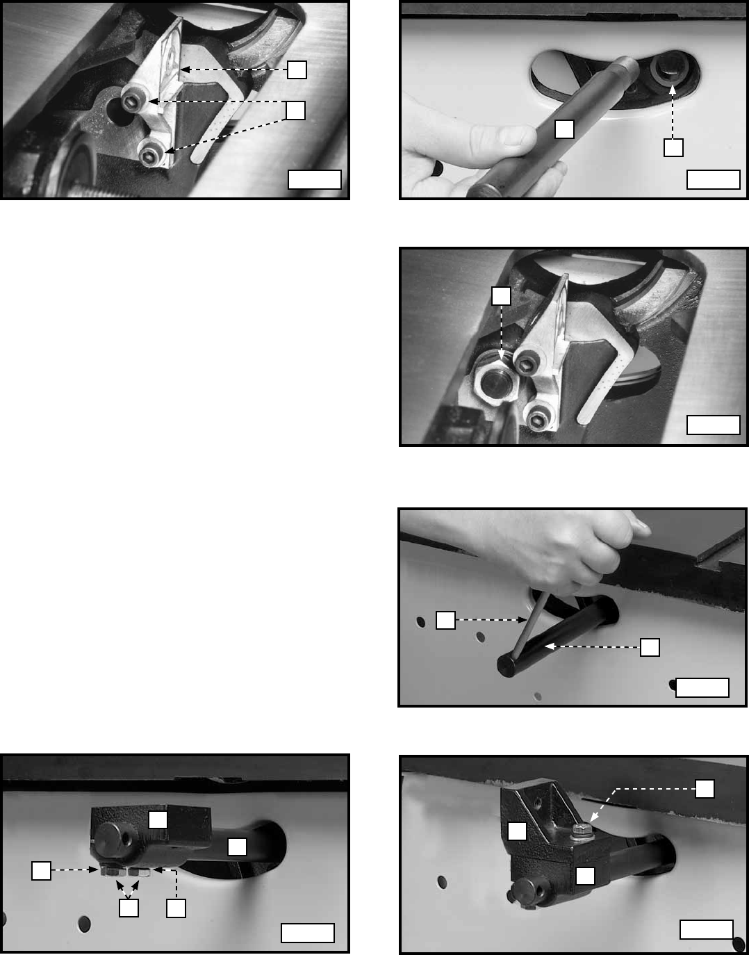
5. To adjust, loosen the two screws (F) Fig. 12. Adjust the
splitter bracket (A) until it is aligned with the inside blade
flange (B) Fig. 11. Tighten the two screws (F). Loosely
attach the screw and fastener plate that were removed
earlier.
6. Insert the threaded end of the support rod (G) Fig. 13
through the slot in the rear of the saw and into hole in the
rear trunnion (H). Fasten the support rod (G) to the trunnion
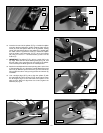
with a star washer and a 5/8-18 hex jam nut (J) Fig. 14.
NOTE: Thread the nut (J) Fig. 14 on the threads of the support
rod (G) as far as possible by hand.
7. Use a wrench to hold the jam nut (J) Fig. 14. Tighten
the rod (G) Fig. 15 with a small screwdriver (K) or similar
device through the hole in the end of the rod.
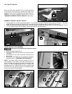
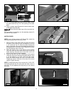
8. Loosely attach the lower bracket (L) Fig. 16 to the rod
(G) with two 5/16-18 x 1” hex-head screws (S) and 5/16”
lockwashers (T) from underneath the bracket (L).
9. Align the hole in the upper splitter bracket (M) Fig. 17 with
the hole in the lower splitter bracket (L). Place a 5/16”
lockwasher, then a 5/16” flat washer on a 5/16-18 x 1”
hex-head screw (N). Insert the screw (N) through the hole
in the upper splitter bracket (M) and thread the screw in
the lower splitter bracket (L).
NOTE: Loosely tighten the screw (N) for further adjustment.
A
F
G
H
J
K
G
L
T
S
T
G
M
L
N
Fig. 12 Fig. 13
Fig. 14
Fig. 15
Fig. 16
Fig. 17


