


11- ENG
Westward Operating Instructions and Parts Manual Model 3JR70A
Portable Air Compressor
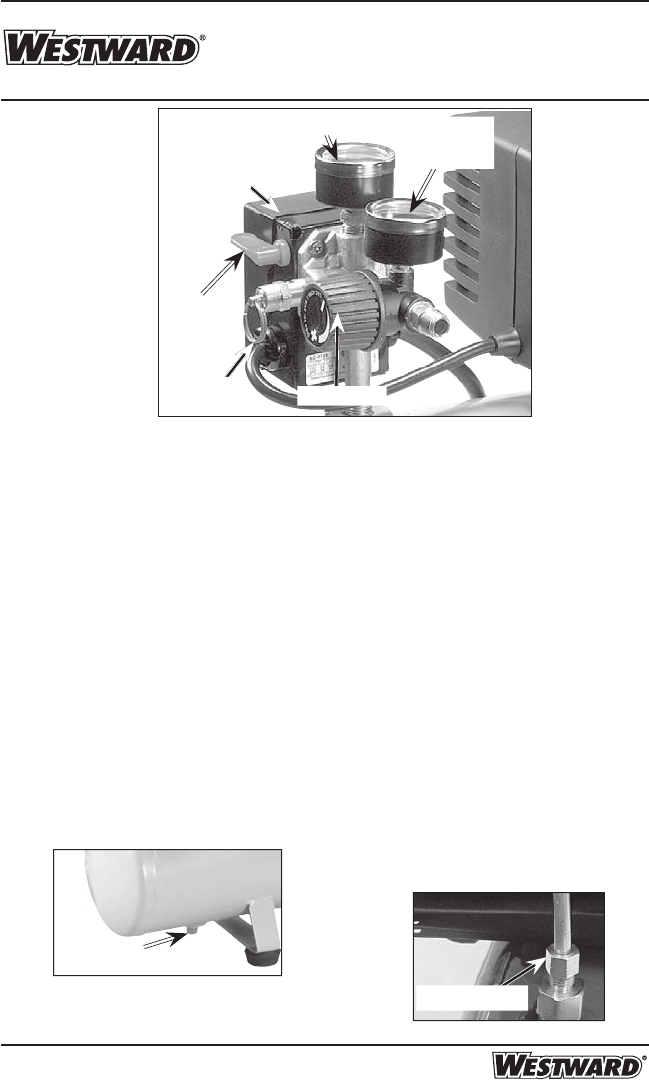
Description of Operation (continued)
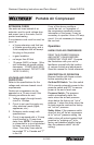
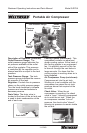
Outlet Pressure Gauge: The
outlet pressure gauge indicates the
air pressure available at the outlet
side of the regulator. This pressure
is controlled by the regulator and is
always less than or equal to the tank
pressure.
Tank Pressure Gauge: The tank
pressure gauge indicates the reserve
air pressure in the tank.
Regulator: Controls the air pressure
shown on the outlet pressure gauge.
Turn the knob clockwise to increase
pressure and counterclockwise to
decrease pressure.
Drain Valve: The drain valve is
located at the base of the air tank and
is used to drain condensation at the
end of each use.
On/
Auto/Off
Switch
Cooling System (not shown)
: This
compressor contains an advanced
design cooling system. At the heart of
this cooling system is an engineered
fan. It is perfectly normal for this fan
to blow air through the vent holes in
large amounts. You know that the
cooling system is working when air is
being expelled.
Air Compressor Pump (not shown):
Compresses air into the air tank.
Working air is not available until the
compressor has raised the air tank
pressure above that required at the
air outlet.
Check Valve:
When the air
compressor is operating, the check
valve is "open", allowing compressed
air to enter the air tank. When the
air compressor reaches "cut-out"
pressure, the check valve "closes",
allowing air pressure to remain inside
the air tank.
Check Valve
Regulator
Safety
Valve
Outlet
Pressure
Gauge
Tank Pressure Gauge
Pressure
Switch
Drain Valve