


INTENDED USE
The heavy-duty V.S.R. drills are designed for professional drilling at various work sites (i.e.,
construction sites). DO NOT use under wet conditions or in presence of flammable liquids or
gases.
These heavy-duty V.S.R. drills are professional power tools. DO NOT let children come into
contact with the tool. Supervision is required when inexperienced operators use this tool.
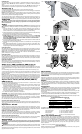
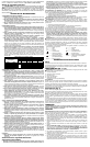
Switches (Fig. 1)
To start the drill, depress the trigger switch; to stop the drill, release the trigger.
A variable speed trigger switch (A) permits speed control—the farther the trigger is depressed,
the higher the speed of the drill.
NOTE: Use lower speeds for starting holes without a center punch, drilling in metal or plastics,
driving screws or drilling ceramics. Higher speeds are better for drilling wood and composition
boards and using abrasive and polishing accessories.
The reversing lever (B) is used for withdrawing bits from tight holes and removing screws. It is
located above the trigger switch. To reverse the motor, release the trigger switch FIRST and
then push the lever to the right. After any reversing operations, return lever to forward position.
OPERATION
WARNING: To reduce the risk of serious personal injury, turn tool off and disconnect
tool from power source before making any adjustments or removing/installing attach-
ments or accessories.
Drilling
WARNING: To reduce the risk of personal injury, ALWAYS ensure workpiece is anchored
or clamped firmly. If drilling thin material, use a wood “back-up” block to prevent damage to the
material.
1. Use sharp drill bits only. For WOOD, use twist drill bits, spade bits, power auger bits, or
hole saws. For METAL, use steel twist drill bits or hole saws. For MASONRY, such as brick,
cement, cinder block, etc., use carbide-tipped bits rated for percussion drilling.
2. Always apply pressure in a straight line with the bit. Use enough pressure to keep drill biting,
but do not push hard enough to stall the motor or deflect the bit.
3. Hold tool firmly with both hands to control the twisting action of the drill.
4. IF DRILL STALLS, it is usually because it is being overloaded or improperly used. RELEASE
TRIGGER IMMEDIATELY, remove drill bit from work, and determine cause of stalling. DO
NOT CLICK TRIGGER ON AND OFF IN AN ATTEMPT TO START A STALLED DRILL —
THIS CAN DAMAGE THE DRILL.
5. To minimize stalling or breaking through the material, reduce pressure on drill and ease the
bit through the last fractional part of the hole.
6. Keep the motor running when pulling the bit back out of a drilled hole. This will help prevent
jamming.
7. With variable speed drills there is no need to center punch the point to be drilled. Use a
slow speed to start the hole and accelerate by squeezing the trigger harder when the hole
is deep enough to drill without the bit skipping out.
DRILLING IN METAL
Start drilling with slow speed and increase to full power while applying firm pressure on the tool.
A smooth even flow of metal chips indicates the proper drilling rate. Use a cutting lubricant when
drilling metals. The exceptions are cast iron and brass which should be drilled dry.
NOTE: Large [5/16" (8 mm) to 1/2" (13 mm)] holes in steel can be made easier if a pilot hole
[5/32" (4 mm) to 3/16" (5 mm)] is drilled first.
DRILLING IN WOOD
Start drilling with slow speed and increase to full power while applying firm pressure on the tool.
Holes in wood can be made with the same twist drills used for metal. These bits may overheat
unless pulled out frequently to clear chips from the flutes. Work that is apt to splinter should be
backed up with a block of wood.
DRILLING IN MASONRY
When drilling in masonry, use carbide-tipped bits rated for percussion drilling and be certain that
the bits are sharp. Use a constant and firm force on the tool to drill most effectively. A smooth,
even flow of dust indicates the proper drilling rate.
Bubble Level – DWD110, DWD112, DWD115 (Fig. 2)
Your drill is equipped with a bubble level (C) that assists you in drilling level holes.
For horizontal drilling, tilt the drill up or down as required so that the bubble floats in the center
of the parallel lines drawn on the glass. When the bubble is centered between the lines, the drill
is level.
For vertical drilling, align the drill so that the bubble floats in the center of the bull’s-eye, (D).
To assure accuracy, first place a level on your work piece and position it so that it is level. Then,
when the drill reads level, the two will be aligned. (Any bubble level can only indicate level to
the earth’s surface).
NOTE: The fluid in the bubble level vial is mineral spirits. If the mineral spirits gets into your
eyes, flush eyes with water. If irritation occurs, seek medical attention. If the vial fluid comes into
contact with your skin, remove contaminated clothing and remove excess fluid. Rinse thoroughly
with water followed by washing with soap and water. If irritation occurs, seek medical attention. If
vial fluid is inhaled, immediately get fresh air. If difficulty breathing, seek medical attention.
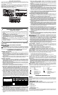
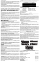
Keyless Chuck – D21007, D21008, D21009, DWD110,
DWD115 (Fig. 3)
Your tool features a keyless chuck (E) for greater convenience. To insert a drill bit or other
accessory, follow the steps listed below.
1. Grasp the rear half of the chuck with one hand and use your other hand to rotate the front
half counterclockwise, as shown in Figure 3. Rotate far enough so that the chuck opens
sufficiently to accept the desired accessory.
2. Insert the bit or other accessory about 3/4" (19 mm) into the chuck and tighten securely by
holding the rear half of the chuck and rotating the front portion in the clockwise direction.
When the chuck is nearly tightened, you will hear a clicking sound. After 4–6 clicks, the
chuck is securely tightened around the accessory.
3 To release the accessory, repeat step 1 listed above.
WARNING: Do not attempt to tighten drill bits (or any other accessory) by gripping the front
part of the chuck and turning the tool on. Damage to the chuck and personal injury may result.
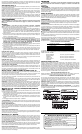
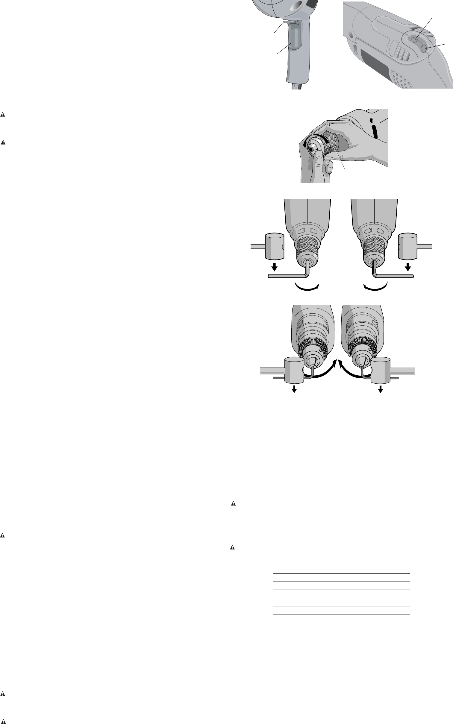
KEYLESS CHUCK REMOVAL (FIG. 4)
Tighten the chuck around the shorter end of a hex key (not supplied) of 1/4" (6 mm) or greater
size. Using a soft hammer or piece of wood, strike the longer end in the counterclockwise direc-
tion. This will loosen the chuck so that it can be unscrewed by hand.
KEYLESS CHUCK INSTALLATION (FIG. 5)
Screw the chuck on by hand as far as it will go. Tighten the chuck around the shorter end of a
1/4" (6 mm) or larger hex key (not supplied) strike the longer end in the clockwise direction with
a soft hammer.
Keyed Chuck – D21002
Open the chuck jaws by turning collar by hand and insert the shank of the bit about
3/4" (19 mm)
into chuck. Tighten the chuck collar by hand. Place chuck key in each of the three holes, and tighten
in clockwise direction. It’s important to tighten chuck with all three holes. To release the bit, turn the
chuck counterclockwise in just one hole, then loosen the chuck by hand.
REMOVAL OF KEYED CHUCK (FIG. 6)
Tighten the chuck around the shorter end of a hex key (not supplied) of 1/4" (6 mm) or greater
size. Using a soft hammer, strike the key sharply in the counterclockwise direction when viewed
from the front of the tool. This will loosen the chuck
so that it can be removed by hand.
KEYED CHUCK INSTALLATION (FIG. 7)
Screw the chuck on by hand as far as it will go. Insert the shorter end of a hex key (not supplied)
of 1/4" (6 mm) or greater size and strike it in the clockwise direction with a soft hammer.
MAINTENANCE
WARNING: To reduce the risk of serious personal injury, turn tool off and disconnect
tool from power source before making any adjustments or removing/installing attachments
or accessories.
Cleaning
WARNING: Never use solvents or other harsh chemicals for cleaning the non-metallic parts
of the tool. These chemicals may weaken the plastic materials used in these parts. Use a cloth
dampened only with water and mild soap. Never let any liquid get inside the tool; never immerse
any part of the tool into a liquid.
FIG. 5
FIG. 4
FIG. 6
FIG. 7
FIG. 2
C
D
Motor Brushes
DEWALT uses an advanced brush system which automatically stops the drill when the brushes
wear out. This prevents serious damage to the motor. New brush assemblies are available at
authorized D
EWALT service centers. Always use identical replacement parts.
Lubrication
When the tool is taken apart for motor brush replacement a small amount of grease should be
added (or redistributed from that remaining in housing) to the gears. The ball bearings used in
this tool are lubricated during manufacture and require no lubrication.
Repairs
To assure product SAFETY and RELIABILITY, repairs, maintenance and adjustments (including
brush inspection and replacement) should be performed by a DEWALT factory service center,
a D
EWALT authorized service center or other qualified service personnel. Always use identical
replacement parts.
Accessories
WARNING: Since accessories, other than those offered by DEWALT, have not been tested
with this product, use of such accessories with this tool could be hazardous. To reduce the risk
of injury, only D
EWALT, recommended accessories should be used with this product.
Recommended accessories for use with your tool are available at extra cost from your local
service center.
If you need assistance in locating any accessory, please contact D
EWALT Industrial Tool Co.,
701 East Joppa Road, Baltimore, MD 21286 or call 1-800-4-D
EWALT (1-800-433-9258).
CAUTION: To reduce the risk of injury, the following accessories should be used only in sizes
up to the maximums shown in the table below.
MAXIMUM RECOMMENDED CAPACITIES
Drill capacity 3/8" (10 mm)
R.P.M. 0-2500
Bits, metal drilling 3/8" (10 mm)
Wood, flat boring 1" (25.4 mm)
Bits, masonry drilling 1/2" (12.7 mm)
Hole saws 1-1/8" (28.4 mm)
ACCESSORY MUST BE RATED FOR USE AT SPEED EQUAL TO OR HIGHER THAN
NAMEPLATE R.P.M. OF TOOL WITH WHICH IT IS BEING USED.
Wire wheel brushes 4" (101.6 mm) diameter maximum
Wire cup brushes 3" (76.2 mm) diameter maximum
Buffing wheels 3" (76.2 mm) diameter maximum
Rubber backing pads 4-5/8" (117.4 mm) diameter maximum
Three Year Limited Warranty
DEWALT will repair, without charge, any defects due to faulty materials or workmanship for
three years from the date of purchase. This warranty does not cover part failure due to normal
wear or tool abuse. For further detail of warranty coverage and warranty repair information, visit
www.dewalt.com or call 1-800-4-D
EWALT (1-800-433-9258). This warranty does not apply to
accessories or damage caused where repairs have been made or attempted by others. This
warranty gives you specific legal rights and you may have other rights which vary in certain
states or provinces.
In addition to the warranty, D
EWALT tools are covered by our:
1 YEAR FREE SERVICE
D
EWALT will maintain the tool and replace worn parts caused by normal use, for free, any time
during the first year after purchase.
A
B
FIG. 1
FIG. 3
E