


7
English
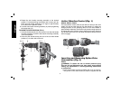
symbol (R) on the toolholder. If inserted correctly,the locking
sleeve (P) moves back to the end position and shows a closed
lock symbol.
2. Pull on the bit to be sure that it is properly locked.
3. If the chisel groove is not aligned with the symbol, or is not
inserted to the complete depth the lock symbol remains open.
To remove the bit, pull back the locking sleeve and pull the bit out.
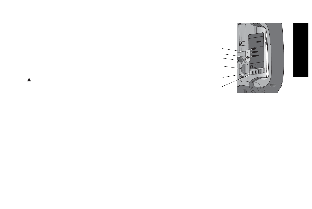
Inserting and Removing SDS Max
®
Accessories
D25501, D25602, D25831
WARNING: To reduce the risk of serious personal injury,
turn tool off and disconnect tool from power source before
making any adjustments or removing/installing attachments
or accessories.
1. Pull back the locking sleeve (P) and insert the bit shank. The bit
shank must be clean.
2. Turn the bit slightly until the sleeve snaps back into position.
3. Ensure the bit is properly engaged.
NOTE: The bit needs to move several centimeters in and out of
the tool holder (M) when properly engaged.
4. To remove the bit, pull back the locking sleeve and pull the bit
out.
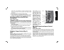
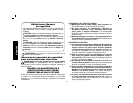
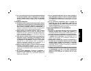
Complete Torque Control (Fig. 5)
D25602
NOTICE: Always turn the tool off before changing torque control
settings or damage to tool may result.
The Complete Torque Control (CTC) feature of this tool is designed
to provide additional control with a two-stage clutch mechanism.
Clutch Setting 1 (S) is designed for most hammerdrilling applications
and is designed to easily clutch out when the drill bit encounters
re-bar or other foreign substances.
Clutch Setting 2 (T) is
W
CTC
COMPLETE TORQUE CONTROL
D
E
W
A
L
T INDUSTRIAL TOOL CO., BA
L
TIMORE, MD 21286 USA
FOR SERVICE INFORMA
TION, CALL 1-800-4-D
E
W
A
L
T
ww
w
.D
E
W
A
L
T
.com
SER.
D25XXX
1 3/4" (44mm) SDS MAX
ROTARY HAMMER
AFIN DE MINIMISER
LES RISQUES DE
BLESSURES,
L
’UTILIS
A
TEUR DOIT LIRE LE GUIDE
D’UTILIS
A
TION.TOUJOURS UTILISER UNE PROTECTION
OCULAIRE,
AUDITIVE ET RESPIR
A
TOIRE ADÉQU
A
TE.
UTILISER LA POIGNÉE L
A
TÉRALE.
LEA EL MANUAL DE
INSTRUCCIONES PARA
UN FUNCIONAMIENTO SEGURO. SIEMPRE UTILICE
PROTECCIÓN ADECUADA
PARA LOS OJOS, OÍDOS Y VÍAS
RESPIR
A
TORIAS. SIEMPRE UTILICE EL MANGO LATERAL.
TO REDUCE THE RISK OF INJUR
Y,
USER MUST READ INSTRUCTION
MANUAL. A
LWA
YS USE PROPER EYE, EAR AND
RESPIR
ATO
RY PROTECTION. A
LW
A
YS USE SIDE HANDLE.
Service
Lock-On
B
r
ush Se
rvice
WARNING
AVERTISSEMENT
ADVERTENCIA
1
2
FIG. 5
G
V
S
T
U
designed for higher torque
applications such as core-
bits and deep hole
hammerdrilling and is
designed to clutch out at a
higher torque threshold.
Move the torque control
lever (U) to setting 1 or 2
as needed for application.
NOTE: Allow the motor
housing to rotate a little
while changing torque.
Each time the tool
is plugged in, it will
automatically default to
clutch setting 1, the most
sensitive setting.
Electronic Speed and Impact Control
(Fig. 5)
D25602, D25831, D25851
The electronic speed and impact control allows the use of smaller
drill bits without the risk of bit breakage, hammerdrilling into light
and brittle materials without shattering and optimal tool control for
precise chipping.
To set the control dial, turn the dial (G) to the desired level. The
higher the number, the greater the speed and impact energy. Dial
settings make the tool extremely adaptable for many different
appli cations. The required setting depends on the bit size and
hardness of material being drilled.