


11
English
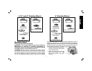
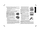
Hubbed wheels install directly on the 5/8-11 threaded spindle.
Thread of accessory must match thread of spindle.
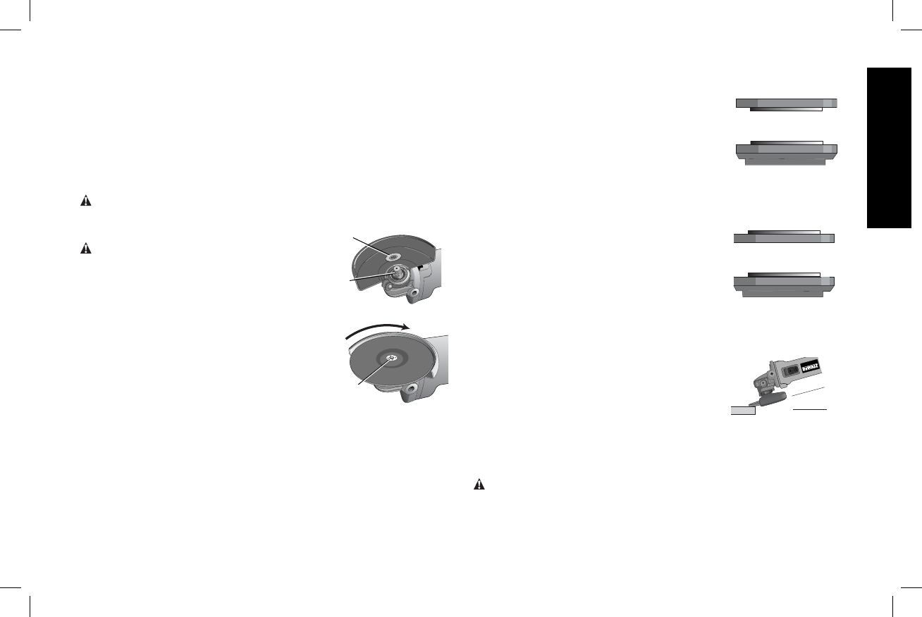
1. Backing flange is retained to the grinder by an O-ring on the
spindle. Remove backing flange by pulling and twisting flange
away form the machine.
2. Thread the wheel on the spindle by hand.
3. Depress the spindle lock button and use a wrench to tighten the
hub of the wheel.
4. Reverse the above procedure to remove the wheel.
CAUTION: Failure to properly seat the wheel before turning the
tool on may result in damage to the tool or the wheel.
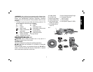
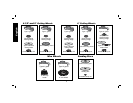
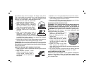
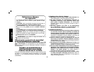
MOUNTING NON-HUBBED WHEELS
G
D
WARNING: Turn off and unplug the
tool before making any adjustments or
removing or installing attachments or
accessories. Before reconnecting the
tool, turn the switch on and off as
previously described to ensure that the
tool is off.
Depressed center Type 27 grinding wheels
H
must be used with included flanges.
1. Be sure the backing flange recess is
seated onto the flats of the spindle by
pushing and twisting the flange before
placing wheel.
2. Place wheel against the backing flange, centering the wheel on
the raised section (pilot) of the backing flange.
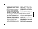
3. While depressing the spindle lock button, thread the clamp nut
(H) on spindle. If the wheel you are installing is more than 1/8"
(3.17mm) thick, place the threaded clamp nut on the spindle so
that the raised section (pilot) fits into the center of the wheel.
If the wheel you are installing is 1/8" (3.17mm) thick or less,
place the threaded clamp nut on the spindle so that the raised
section (pilot) is not against the wheel.
4. While depressing the spindle lock button,
1/4" WHEELS
(6.35 mm)
Quick-Change
backing flange
threaded clamp nut
1/8" WHEELS
(3.17 mm)
threaded clamp nut
Quick-Change
backing flange
tighten the clamp nut with a wrench.
5. To remove the wheel, depress the
spindle lock button and loosen the
threaded clamp nut with a wrench.
NOTE: If the wheel spins after the clamp
nut is tightened, check the orientation of
the threaded clamp nut. If a thin wheel is
installed with the pilot on the clamp nut
against the wheel, it will spin because the
height of the pilot prevents the clamp nut
from holding the wheel.
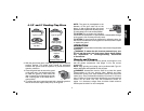
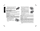
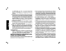
SURFACE GRINDING WITH GRINDING
WHEELS
1. Allow the tool to reach full speed before
touching the tool to the work surface.
2. Apply minimum pressure to the work
surface, allowing the tool to operate at
high speed. Grinding rate is greatest
when the tool operates at high speed.
3. Maintain a 20˚ to 30˚ angle between the
20˚-30˚
tool and work surface.
4. Continuously move the tool in a forward
and back motion to avoid creating gouges
in the work surface.
5. Remove the tool from work surface before turning tool off. Allow
the tool to stop rotating before laying it down.
EDGE GRINDING WITH GRINDING WHEELS
CAUTION: Wheels used for cutting and edge grinding may break
if they bend or twist while the tool is being used to do cut-off work or
deep grinding. To reduce the risk of serious injury, limit the use of
these wheels with a standard Type 27 guard to shallow cutting and
notching (less than 1/2" in depth). The open side of the guard must