


COMPONENTS
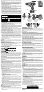
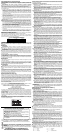
Variable Speed Switch (Fig. 1)
To turn the tool on, squeeze the trigger switch (A). To turn the tool off, release the trigger
switch. Your tool is equipped with a brake. The chuck will stop as soon as the trigger switch is fully
released.
NOTE: Continuous use in variable speed range is not recommended. It may damage the switch
and should be avoided.
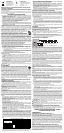
Forward/Reverse Control Button (Fig. 1, 4)
A forward/reverse control button (B) determines the direction of the tool and also serves as a lock
off button. To select forward rotation, release the trigger switch and depress the forward/reverse
control button on the right side of the tool. To select reverse, depress the forward/reverse control
button on the left side of the tool. The center position of the control button locks the tool in the off
position. When changing the position of the control button, be sure the trigger is released.
NOTE: The first time the tool is run after changing the direction of rotation, you may hear a click on
start up. This is normal and does not indicate a problem.
Torque Adjustment Collar (Fig. 1)
The torque adjustment collar (C) is clearly marked with numbers and a drill bit symbol.The collar
should be rotated until the desired setting is located at the top of the tool (Fig. 1). Locators are
provided in the collar to eliminate the guess work when selecting fastening torque. The higher the
number on the collar, the higher the torque and the larger the fastener which can be driven. To lock
the clutch for drilling operations, move to the drill bit position.
NOTE: When using the drill/driver for drilling holes, be sure that the torque adjusting collar is set so
the figure of the drill is aligned with the center line on the top of the tool. Failure to do this will allow
the clutch to slip while attempting to drill.
Dual Range Gearing (Fig. 1)
The dual range feature of your driver/drill allows you to shift gears for greater versatility.
To select the low speed, high torque setting, turn the tool off and permit to stop. Slide the gear shifter
(D) forward (towards the chuck). To select the high speed, low torque setting, turn the tool off and
permit to stop. Slide the gear shifter back (away from chuck).
NOTE Do not change gears when the tool is running. If you are having trouble changing gears,
make sure that the dual range gear shifter is either completely pushed forward or completely pushed
back.
Keyless Single Sleeve Chuck
Your tool features a keyless chuck with one rotating sleeve for one-handed operation of the chuck.
To insert a drill bit or other accessory, follow these steps.
1. Lock the trigger in the OFF position as previously described.
2. Grasp the black sleeve of the chuck with one hand and use the other hand to secure the tool.
Rotate the sleeve counterclockwise far enough to accept the desired accessory.
3. Insert the accessory about 3/4" (19 mm) into the chuck and tighten securely by rotating the
chuck sleeve clockwise with one hand while holding the tool with the other. Your tool is equipped
with an automatic spindle lock mechanism. This allows you to open and close the chuck with
one hand.
To release the accessory, repeat step 2 above.
WARNING: Do not attempt to tighten drill bits (or any other accessory) by gripping the front part
of the chuck and turning the tool on. Damage to the chuck and personal injury may result. Always
lock off trigger switch when changing acces sories.
Be sure to tighten chuck with one hand on the chuck sleeve and one hand holding the tool for
maximum tightness.
OPERATION
WARNING: To reduce the risk of serious personal injury, turn tool off and disconnect
tool from power source before making any adjustments or removing/installing attachments
or accessories.
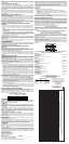
Installing and Removing the Battery Pack (Fig. 2, 3)
NOTE: Make sure your battery pack is fully charged.
To install the battery pack into the tool handle, align the notch inside the tool’s handle with
the battery pack and slide the battery pack firmly into the handle until you hear the lock snap
into place.
To remove the battery pack from the tool, press the release buttons (E) and firmly pull the
battery pack out of the tool handle. Insert it into the charger as described in the charger section
of this manual.
Drill Operation
WARNING: To reduce the risk of serious personal injury, turn tool off and disconnect tool
from power source before making any adjustments or removing/installing attachments
or accessories.
WARNING: To reduce the risk of personal injury, ALWAYS ensure workpiece is anchored
or clamped firmly. If drilling thin material, use a wood “back-up” block to prevent damage to the
material.
Turn the collar to the drill bit symbol for drilling. Select the desired speed/torque range using the gear
shifter to match the speed and torque to the planned operation.
1. Use sharp drill bits only. For WOOD, use the low speed setting and twist drill bits, spade bits,
power auger bits, or hole saws. For METAL, use the low speed setting and steel twist drill bits
or hole saws. For MASONRY, such as brick, cement, cinder block, etc., use carbide-tipped
bits rated for percussion drilling. Use low speed for bits greater than 3/8" (10 mm).
2. Always apply pressure in a straight line with the bit. Use enough pressure to keep drill biting,
but do not push hard enough to stall the motor or deflect the bit.
3. Hold tool firmly with both hands to control the twisting action of the drill. If model is not
equipped with side handle, grip drill with one hand on the handle and one hand on the battery
pack.
CAUTION: Drill may stall if overloaded causing a sudden twist. Always expect the stall. Grip
the drill firmly to control the twisting action and avoid injury.
4. IF DRILL STALLS, it is usually because it is being overloaded or improperly used. RELEASE
TRIGGER IMMEDIATELY, remove drill bit from work, and determine cause of stalling. DO
NOT CLICK TRIGGER ON AND OFF IN AN ATTEMPT TO START A STALLED DRILL —
THIS CAN DAMAGE THE DRILL.
5. To minimize stalling or breaking through the material, reduce pressure on drill and ease the
bit through the last fractional part of the hole.
6. Keep the motor running when pulling the bit back out of a drilled hole. This will help prevent
jamming.
7. With variable speed drills there is no need to center punch the point to be drilled. Use a
slow speed to start the hole and accelerate by squeezing the trigger harder when the hole
is deep enough to drill without the bit skipping out.
Operation as a Screwdriver
Select the desired speed/torque range using the dual range gear shifter on the top of tool to
match the speed and torque to the planned operation.
Insert the desired fastener accessory into the chuck as you would any drill bit. Make a few
practice runs in scrap or unseen areas to determine the proper position of the clutch collar.
MAXIMUM RECOMMENDED CAPACITIES
DC727, DC728 DC759, DC970
WOOD 1-1/2" 1-1/2"
STEEL 3/8" 1/2"
MAINTENANCE
WARNING: To reduce the risk of serious personal injury, turn tool off and disconnect
tool from power source before making any adjustments or removing/installing attachments
or accessories.
buildup of metallic particles should be kept away from charger cavities. Always unplug the
charger from the power supply when there is no battery pack in the cavity. Unplug charger before
attempting to clean.
• DO NOT attempt to charge the battery pack with any chargers other than the ones in
this manual. The charger and battery pack are specifically designed to work together.
• These chargers are not intended for any uses other than charging D
EWALT rechargeable
batteries. Any other uses may result in risk of fire, electric shock or electrocution.
• Do not expose charger to rain or snow.
• Pull by plug rather than cord when disconnecting charger. This will reduce risk of
damage to electric plug and cord.
• Make sure that cord is located so that it will not be stepped on, tripped over, or
otherwise subjected to damage or stress.
• Do not use an extension cord unless it is absolutely necessary. Use of improper
extension cord could result in risk of fire, electric shock, or electrocution.
• When operating a power tool outdoors, use an extension cord suitable for outdoor use.
Use of a cord suitable for outdoor use reduces the risk of electric shock.
• An extension cord must have adequate wire size (AWG or American Wire Gauge) for
safety. The smaller the gauge number of the wire, the greater the capacity of the cable, that
is 16 gauge has more capacity than 18 gauge. An undersized cord will cause a drop in line
voltage resulting in loss of power and overheating. When using more than one extension to
make up the total length, be sure each individual extension contains at least the minimum
wire size. The following table shows the correct size to use depending on cord length and
nameplate ampere rating. If in doubt, use the next heavier gauge. The smaller the gauge
number, the heavier the cord.
Minimum Gauge for Cord Sets
Ampere Rating
Volts Total Length of Cord in Feet (meters)
120V
25 (7.6) 50 (15.2) 100 (30.5) 150 (45.7)
240V
50 (15.2) 100 (30.5) 200 (61.0) 300 (91.4)
More
Than
Not More
Than
AWG
0 6 18 16 16 14
610 18161412
10 12 16 16 14 12
12 16 14 12 Not Recommended
• Do not place any object on top of charger or place the charger on a soft surface that
might block the ventilation slots and result in excessive internal heat. Place the charger
in a position away from any heat source. The charger is ventilated through slots in the top and
the bottom of the housing.
• Do not operate charger with damaged cord or plug.
• Do not operate charger if it has received a sharp blow, been dropped, or otherwise
damaged in any way. Take it to an authorized service center.
• Do not disassemble charger; take it to an authorized service center when service or
repair is required. Incorrect reassembly may result in a risk of electric shock, electrocution
or fire.
• Disconnect the charger from the outlet before attempting any cleaning. This will reduce
the risk of electric shock. Removing the battery pack will not reduce this risk.
• NEVER attempt to connect 2 chargers together.
• The charger is designed to operate on standard 120V household electrical power. Do
not attempt to use it on any other voltage. This does not apply to the vehicular charger.
Using Automatic Tune-Up™ Mode
The automatic Tune-Up™ Mode equalizes or balances the individual cells in the battery pack
allowing it to function at peak capacity. Battery packs should be tuned up weekly or after
10 charge/discharge cycles or whenever the pack no longer delivers the same amount of work.
To use the automatic Tune-Up™, place the battery pack in the charger and leave it for at least
8 hours. The charger will cycle through the following modes.
1. The red light will blink continuously indicating that the 1-hour charge cycle has started.
2. When the 1-hour charge cycle is complete, the light will stay on continuously and will no
longer blink. This indicates that the pack is fully charged and can be used at this time.
3. If the pack is left in the charger after the initial 1-hour charge, the charger will begin the
Automatic Tune-Up mode. This mode continues up to 8 hours or until the individual cells in
the battery pack are equalized. The battery pack is ready for use and can be removed at any
time during the Tune-Up mode.
4. Once the Automatic Tune Up mode is complete, the charger will begin a maintenance
charge; the red indicator will remain lit.
Chargers
Your tool uses a DEWALT 12, 14.4, 18 Volt charger. Be sure to read all safety instructions before
using your charger. Consult the chart at the end of this manual for compatibility of chargers and
battery packs.
Charging Procedure (Fig. 3)
DANGER: Electrocution hazard. 120 volts present at charging terminals. Do not probe with
conductive objects. Danger of electric shock or electrocution.
1. Plug the charger into an appropriate outlet before inserting battery pack.
2. Insert the battery pack into the charger. The red (charging) light will blink continuously
indicating that the charging process has started.
3. The completion of charge will be indicated by the red light remaining ON continuously. The
pack is fully charged and may be used at this time or left in the charger.
Indicator Light Operation
Charge Indicators
Some chargers are designed to detect certain problems that can arise with battery packs.
Problems are indicated by the red light flashing at a fast rate. If this occurs, re-insert battery pack
into the charger. If the problem persists, try a different battery pack to determine if the charger is
OK. If the new pack charges correctly, then the original pack is defective and should be returned
to a service center or other collection site for recycling. If the new battery pack elicits the same
trouble indication as the original, have the charger tested at an authorized service center.
HOT/COLD PACK DELAY
Some chargers have a Hot/Cold Pack Delay feature: when the charger detects a battery that is
hot, it automatically starts a Hot Pack Delay, suspending charging until the battery has cooled.
After the battery has cooled, the charger automatically switches to the Pack Charging mode.
This feature ensures maximum battery life. The red light flashes long, then short while in the Hot
Pack Delay mode.
PROBLEM POWER LINE
Some chargers have a Problem Power Line indicator. When the charger is used with some
portable power sources such as generators or sources that convert DC to AC, the charger may
temporarily suspend operation, flashing the red light with two fast blinks followed by a pause.
This indicates the power source is out of limits.
LEAVING THE BATTERY PACK IN THE CHARGER
The charger and battery pack can be left connected with the red light glowing indefinitely. The
charger will keep the battery pack fresh and fully charged.
NOTE: A battery pack will slowly lose its charge when kept out of the charger. If the battery pack
has not been kept on maintenance charge, it may need to be recharged before use. A battery
pack may also slowly lose its charge if left in a charger that is not plugged into an appropriate
AC source.
WEAK BATTERY PACKS: Chargers can also detect a weak battery pack. Such batteries are
still usable but should not be expected to perform as much work. The charger will indicate to
replace battery pack.
Important Charging Notes
1. Longest life and best performance can be obtained if the battery pack is charged when the
air temperature is between 65°F and 75°F (18°- 24°C). DO NOT charge the battery pack in
an air temperature below +40°F (+4.5°C), or above +105°F (+40.5°C). This is important and will
prevent serious damage to the battery pack.
2. The charger and battery pack may become warm to touch while charging. This is a normal
condition, and does not indicate a problem. To facilitate the cooling of the battery pack after use,
avoid placing the charger or battery pack in a warm environment such as in a metal shed, or an
uninsulated trailer.
3. If the battery pack does not charge properly:
a. Check current at receptacle by plugging in a lamp or other appliance
b. Check to see if receptacle is connected to a light switch which turns power off when you turn
out the lights.
c. Move charger and battery pack to a location where the surrounding air temperature is
approximately 65°F - 75°F (18°- 24°C).
d. If charging problems persist, take the tool, battery pack and charger to your local service
center.
4. The battery pack should be recharged when it fails to produce sufficient power on jobs which
were easily done previously. DO NOT CONTINUE to use under these conditions. Follow the
charging procedure. You may also charge a partially used pack whenever you desire with no
adverse affect on the battery pack.
5. Under certain conditions, with the charger plugged into the power supply, the exposed charging
contacts inside the charger can be shorted by foreign material. Foreign materials of a conductive
nature such as, but not limited to, steel wool, aluminum foil, or any buildup of metallic particles
should be kept away from charger cavities. Always unplug the charger from the power supply
when there is no battery pack in the cavity. Unplug charger before attempting to clean.
6. Do not freeze or immerse charger in water or any other liquid.
WARNING: Shock hazard. Don’t allow any liquid to get inside charger. Electric shock may
result.
CAUTION: Never attempt to open the battery pack for any reason. If the plasti
c housing of the
battery pack breaks or cracks, return to a service center for recycling.
Storage Recommendations
1. The best storage place is one that is cool and dry away from direct sunlight and excess heat or
cold.
2. Long storage will not harm the battery pack or charger. Under proper conditions, they can be
stored for 5 years or more.
FIG. 4
DEPRESS FOR REVERSE
ENFONCER POUR LA
ROTATION ARRIÈRE
ADELANTE
DEPRESS FOR FORWARD
ENFONCER POUR LA
ROTATION AVANT
ATRÁS
FIG. 1
FIG. 3
FIG. 2
E
D
A
B
C
E
DC727