


ENGLISH
12
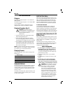
Forward/Reverse Control Button
(fi g. 1)
A forward/reverse control button (b) determines the
direction of the tool and also serves as a lock off
button.
To select forward rotation, release the trigger
switch and depress the forward/reverse control
button on the right side of the tool.
To select reverse, depress the forward/reverse
control button on the left side of the tool.
The center position of the control button locks the
tool in the OFF position. When changing the position
of the control button, be sure the trigger is released.
NOTE: The first time the tool is run after changing
the direction of rotation, you may hear a click on
start up. This is normal and does not indicate a
problem.
Worklight (fi g. 1)
There is a worklight (g) located just above the trigger
switch (a). The worklight will be activated when the
trigger switch is squeezed.
NOTE: The worklight is for lighting the immediate
work surface and is not intended to be used as a
flashlight.
Quick-Release Chuck (fi g. 4)
DC825, DC827, DC835, DC837, DC845
NOTE: The chuck accepts 1/4" hex accessories
only.
Place the switch in the locked off (center) position or
remove battery pack before changing accessories.
To install an accessory, pull the chuck collar (c)
away from the front of the tool, insert the accessory
and release the collar. The accessory is locked in
place.
To remove an accessory, pull the chuck collar
away from the front of the tool. Remove the
accessory and release the collar.
Anvil With Detent Pin (fi g. 5)
DC820, DC822, DC830, DC832, DC840
Place the switch in the locked off (center) position or
remove battery pack before changing accessories.
To install a socket on the anvil, align the hole in
the side of the socket with the detent pin (e) on the
anvil (f). Press the socket on until the detent pin
engages in the hole. Depression of detent pin may
be necessary to aid installation of socket.
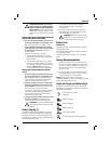
CAUTION: Use only impact sockets.
Non-impact sockets may break and
cause a hazardous condition. Inspect
sock et prior to use to ensure that it
con tains no cracks.
To remove a socket, depress the detent pin
through the hole and pull the socket off.
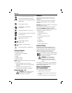
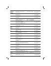
Usage
Your impact tool generates the following output
torque:
Cat # Ft.-Lbs. In.-Lbs. Nm
DC820 145 1740 195
DC822 145 1740 195
DC825 111 1330 150
DC827 111 1330 150
DC830 135 1620 180
DC832 135 1620 180
DC835 103 1240 140
DC837 103 1240 140
DC840 120 1440 160
DC845 96 1150 130
CAUTION: Ensure fastener and/or
system will withstand the level of torque
generated by the tool. Excessive torque
may cause breakage and possible
personal injury.
1. Place the socket on the fastener head. Keep
the tool pointed straight at the fastener.
2. Press switch to start operation. Always check
torque with a torque wrench, as the fastening
torque is affected by many factors including the
following:
• Voltage: Low voltage, due to a nearly
discharged battery, will reduce fastening
torque.
• Socket size: Failure to use the correct
socket size will cause a reduction in fastening
torque.
• Bolt Size: Larger bolt diameters generally
require higher fastening torque. Fastening
torque will also vary according to length,
grade, and torque coefficient.
• Bolt: Ensure that all threads are free of rust
and other debris to allow proper fastening
torque
• Material: The type of material and surface
finish of the material will affect fastening
torque.