


RBRC™ in cooperation with DEWALT and other battery users, has established programs in the
United States to facilitate the collection of spent lithium ion batteries. Help protect our environ-
ment and conserve natural resources by returning the spent lithium ion battery to an authorized
D
EWALT service center or to your local retailer for recycling. You may also contact your local
recycling center for information on where to drop off the spent battery.
RBRC™ is a registered trademark of the Rechargeable Battery Recycling Corporation.
Storage Recommendations
1. The best storage place is one that is cool and dry away from direct sunlight and excess heat
or cold.
2. Long storage will not harm the battery pack or charger. Under proper conditions, they can be
stored for 5 years or more.
Charger
Your battery pack requires a 1 hour DEWALT charger. Be sure to read all safety instructions
before using your charger. Consult the chart on the back of this manual for compatibility of
chargers and battery packs.
Charging Procedure
1. Plug the charger into an appropriate outlet before inserting the battery pack.
2. Insert the battery pack into the charger. The charger is equipped with a three-light fuel gauge
that will blink according to the state of charge of the battery pack.
3. The completion of charge is indicated by the three red lights remaining ON continuously. The
pack is fully charged and may be used at this time or left on the charger.
0% - 33% 1
st
light blinks
33% - 66% 1
st
light on, 2
nd
light blinks
66% - 99% 1
st
, 2
nd
lights on, 3
rd
light blinks
100% 1
st
, 2
nd
, 3
rd
lights on
Charger Diagnostics
This charger is designed to detect certain problems that can arise with the battery packs or the
charger. Problems are indicated by the three red lights flashing together in different patterns.
PROBLEM POWER LINE
When the charger is used with some portable power sources such as generators or sources
that convert DC to AC, the charger may temporarily suspend operation. The three red lights will
flash together with two fast blinks followed by a pause. This indicates that the power source
is out of limits.
BAD BATTERY
The charger can detect a weak or damaged battery. The three red lights will flash together with
rapid blinking. The battery will no longer charge and should be returned to a service center or
a collection site for recycling.
BAD CHARGER
The charger will detect if it is not functioning properly. The three red lights will flash together
with one fast blink followed by a long blink. The charger will no longer work and should be
returned to an authorized service center or replaced.
LEAVING THE BATTERY IN THE CHARGER
The charger and battery pack can be left connected with the red lights glowing indefinitely. The
charger will keep the battery pack fresh and fully charged. This charger features an automatic
tune-up mode which equals or balances the individual cells in the battery pack to allow it to
function at peak capacity. Battery packs should be tuned up weekly or whenever the battery no
longer delivers the same amount of work. To use the automatic tune-up mode, place the battery
pack in the charger and leave it for at least 8 hours.
Important Charging Notes
1. Longest life and best performance can be obtained if the battery pack is charged when the
air temperature is between 65°F and 75°F (18°- 24°C). DO NOT charge the battery pack in
an air temperature below +40°F (+4.5°C), or above +105°F (+40.5°C). This is important and
will prevent serious damage to the battery pack.
2. The charger and battery pack may become warm to touch while charging. This is a normal
condition, and does not indicate a problem. To facilitate the cooling of the battery pack after
use, avoid placing the charger or battery pack in a warm environment such as in a metal
shed, or an uninsulated trailer.
3. If the battery pack does not charge properly:
a. Check current at receptacle by plugging in a lamp or other appliance
b. Check to see if receptacle is connected to a light switch which turns power off when you
turn out the lights.
c. Move charger and battery pack to a location where the surrounding air temperature is
approximately 65°F - 75°F (18°- 24°C).
d. If charging problems persist, take the tool, battery pack and charger to your local
service center.
4. The battery pack should be recharged when it fails to produce sufficient power on jobs which
were easily done previously. DO NOT CONTINUE to use under these conditions. Follow the
charging procedure. You may also charge a partially used pack whenever you desire with no
adverse affect on the battery pack.
5. Foreign materials of a conductive nature such as, but not limited to, steel wool, aluminum
foil, or any buildup of metallic particles should be kept away from charger cavities. Always
unplug the charger from the power supply when there is no battery pack in the cavity. Unplug
charger before attempting to clean.
6. Do not freeze or immerse charger in water or any other liquid.
WARNING: Shock hazard. Do not allow any liquid to get inside charger.
CAUTION: Never attempt to open the battery pack for any reason. If the plastic housing of the
battery pack breaks or cracks, return to a service center for recycling.
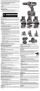
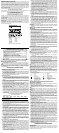
KEY FEATURES AND FUNCTIONS
Variable Speed Switch (Fig. 1)
To turn the tool on, squeeze the trigger switch (A). To turn the tool off, release the trigger switch.
Your tool is equipped with a brake. The chuck will stop as soon as the trigger switch is fully
released.
NOTE: Continuous use in variable speed range is not recommended. It may damage the switch
and should be avoided.
Forward/Reverse Control Button (Fig. 1)
A forward/reverse control button (B) determines the direction the tool will spin and also serves
as a lock-off button.
To select forward rotation, release the trigger switch and depress the for ward/re verse control
button on the right side of the tool.
To select reverse, depress the forward/reverse control button on the left side of the tool.
The center position of the control button locks the tool in the OFF position. When changing the
position of the control button, be sure the trigger is released.
NOTE: The first time the tool is run after changing the direction of rotation, you may hear a click
on start up. This is normal and does not indicate a problem.
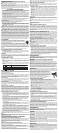
Mode Control Collar
Your drill is equipped with a separate mode control collar (Fig. 1, C) to switch between drilling,
screwdriving and hammerdrilling mode.
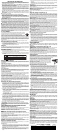
SCREWDRIVING (FIG. 2)
1. Select the desired speed/torque range using the three-speed gear shifter (E) on the top of
tool to match the speed and torque to the planned application. To set the torque level to the
proper setting on the clutch collar, initially set the clutch collar at a lower setting to ensure
the fastener to be set to your specification.
NOTE: Use the lowest torque setting required to seat the fastener at the desired depth. The
lower the number, the lower the torque output.
2. Rotate the mode control collar (C) so the screw symbol is aligned with the arrow.
3. Set the torque adjustment collar (D) to the appropriate number setting for the torque
desired.
NOTE: The torque adjustment collar may be set on any number and change between screw-
driving and drilling modes using the mode control collar.
DRILLING (FIG. 3)
CAUTION: When the mode collar is in the drill/hammerdrill mode, the drill will not clutch out
regardless of the position of the torque adjustment collar (D).
Rotate the mode control collar (C) so the drill symbol is aligned with the arrow.
NOTE: The torque adjustment collar (D) may be set on any number.
HAMMERDRILLING (FIG. 4)
Rotate the mode control collar (C) so the hammer symbol is aligned with the arrow.
Torque Adjustment Collar (Fig. 2)
Your tool has an adjustable torque screwdriver mechanism for driving and removing a wide array
of fastener shapes and sizes and a hammer mechanism for drilling into masonry. Circling the
torque adjustment collar (D) are numbers. These numbers are used to set the clutch to deliver
a torque range. The higher the number on the collar, the higher the torque and the larger the
fastener which can be driven. To select any of the numbers, rotate until the desired number aligns
with the arrow.
Three-Speed Gearing (Fig. 2)
The three-speed feature of your tool allows you to shift gears for greater versatility. To select
speed 1 (highest torque setting), turn the tool off and permit it to stop. Slide the gear shifter (E)
all the way to the left. Speed 2 (middle torque and speed setting) is in the middle position. Speed
3 (highest speed setting) is to the right.
NOTE: Do not change gears when the tool is running. Always allow the drill to come to a com-
plete stop before changing gears. If you have trouble changing gears, make sure that the gear
shifter is engaged in one of the three speed settings.
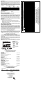
Self-Tightening Chuck Operation (Fig. 5–7)
WARNING: Do not attempt to tighten drill bits (or any other accessory) by gripping the front
part of the chuck and turning the tool on. Damage to the chuck and personal injury may result.
Always lock off trigger switch when changing acces sories.
WARNING: Always ensure the bit is secure before starting the tool. A loose bit may eject
from tool causing possible personal injury.
TO INSERT A DRILL BIT OR OTHER ACCESSORY
1. Lock the trigger in the OFF position.
2. Grasp the chuck sleeve (F) with one hand and use the other hand to secure the tool as
shown in Figure 5. Rotate the sleeve counterclockwise (viewed from the front) far enough to
accept the desired accessory.
3. Insert the bit or other accessory about 3/4" (19 mm) into the chuck, as shown in Figure 6.
Grasp the chuck sleeve securely and rotate the sleeve clockwise (viewed from the front)
with one hand while using the other hand to secure the tool. Rotate the sleeve clockwise
until sleeve cannot be rotated any further, as demonstrated in Figure 7. As the drill is being
operated in the forward position, the chuck will continually self-tighten the jaws of the chuck
onto the bit to maximize the bit gripping strength.
To release the accessory, repeat Step 2.
OPERATION
WARNING: To reduce the risk of serious personal injury, turn tool off and disconnect tool
from battery pack before making any adjustments or removing/installing attachments
or accessories.
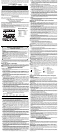
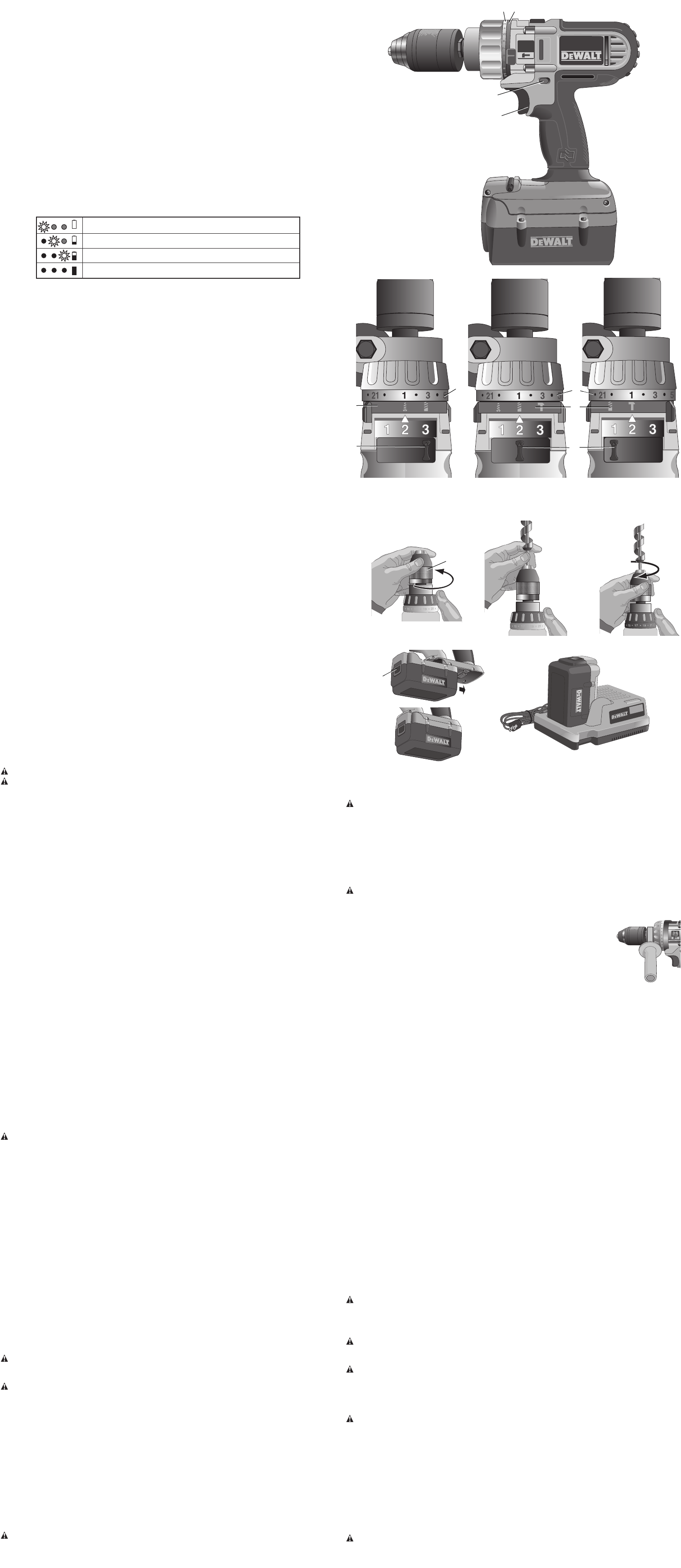
Installing and Removing the Battery Pack (Fig. 8, 9)
NOTE: Make sure your battery pack is fully charged.
CAUTION: Make certain the lock-off button (B), as shown in Figure 1, is engaged to prevent
switch actuation before removing or installing battery.
To install the battery pack into the tool handle, align the base of the tool with the rails inside
the tool’s handle and slide the battery pack firmly into the handle until you hear the lock snap
into place (Fig. 8).
To remove the battery pack from the tool, press the release button (G) and firmly pull the
battery pack out of the tool handle. Insert it into the charger (Fig. 9) as described in the charger
section of this manual.
Side Handle
WARNING: To reduce the risk of personal injury, ALWAYS operate the tool with the side
handle properly installed. Failure to do so may result in the side handle slipping during tool
operation and subsequent loss of control. Hold tool with both hands to maximize control.
Side handle clamps to the front of the gear case as shown and may be
rotated to permit right- or left-hand use. Side handle must be tightened suf-
ficiently to resist the twisting action of the tool if the accessory binds or
stalls. Be sure to grip the side handle at the far end to control the tool during
a stall.
If model is not equipped with side handle, grip drill with one hand on the
handle and one hand on the battery pack.
Drill Operation
1. Select the desired speed/torque range using the gear shifter to match the speed and torque
to the planned operation.
2. For WOOD, use twist bits, spade bits, power auger bits or hole saws. For METAL, use high-
speed steel twist drill bits or hole saws. Use a cutting lubricant when drilling metals. The
exceptions are cast iron and brass which should be drilled dry.
3. Always apply pressure in a straight line with the bit. Use enough pressure to keep the drill bit
biting, but do not push hard enough to stall the motor or deflect the bit.
4. Hold tool firmly with both hands to control the twisting action of the drill.
5. IF DRILL STALLS, it is usually because it is being overloaded. RELEASE TRIGGER
IMMEDIATELY, remove drill bit from work, and determine cause of stalling. DO NOT CLICK
TRIGGER OFF AND ON IN AN ATTEMPT TO START A STALLED DRILL – THIS CAN
DAMAGE THE DRILL.
6. Keep the motor running when pulling the bit back out of a drilled hole. This will help prevent
jamming.
Hammerdrill Operation
1. When drilling, use just enough force on the hammer to keep it from bouncing excessively or
“rising” off the bit. Too much force will cause slower drilling speeds, overheating, and a lower
drilling rate.
2. Drill straight, keeping the bit at a right angle to the work. Do not exert side pressure on the
bit when drilling as this will cause clogging of the bit flutes and a slower drilling speed.
3. When drilling deep holes, if the hammer speed starts to drop off, pull the bit partially out of
the hole with the tool still running to help clear debris from the hole.
4. For MASONRY, use carbide-tipped bits or masonry bits. A smooth, even flow of dust indi-
cates the proper drilling rate.
Screwdriver Operation
Select the desired speed/torque range using the three-speed gear shift lever on the top of tool
to match the speed and torque to the planned operation. Insert the desired fastener accessory
into the chuck as you would any drill bit. Set the torque adjustment collar (D) to the desired
setting. Make a few practice runs in scrap or unseen areas to determine the proper position of
the clutch collar.
MAINTENANCE
WARNING: To reduce the risk of serious personal injury, turn tool off and disconnect tool
from battery pack before making any adjustments or removing/installing attachments
or accessories.
Cleaning
WARNING: Blow dirt and dust out of all air vents with clean, dry air at least once a week. To
minimize the risk of eye injury, always wear ANSI Z87.1 approved eye protection when
performing this.
WARNING: Never use solvents or other harsh chemicals for cleaning the non-metallic parts of
the tool. These chemicals may weaken the plastic materials used in these parts. Use a cloth
dampened only with water and mild soap. Never let any liquid get inside the tool; never immerse
any part of the tool into a liquid.
CHARGER CLEANING INSTRUCTIONS
WARNING: Shock hazard. Disconnect the charger from the AC outlet before cleaning. Dirt and
grease may be removed from the exterior of the charger using a cloth or soft non-metallic brush.
Do not use water or any cleaning solutions.
Repairs
The charger is not serviceable. There are no serviceable parts inside the charger.
READ ALL OF THE INSTRUCTIONS IN THE BATTERY CHARGER SECTION OF THIS
MANUAL BEFORE ATTEMPTING TO CHARGE THE BATTERY PACK FOR YOUR TOOL
To assure product SAFETY and RELIABILITY, repairs, maintenance and adjustment (including
brush inspection and replacement) should be performed by a D
EWALT factory service center,
a D
EWALT authorized service center or other qualified service personnel. Always use identical
replacement parts.
Accessories
WARNING: Since accessories, other than those offered by DEWALT, have not been tested
with this product, use of such accessories with this tool could be hazardous. To reduce the risk
of injury, only D
EWALT, recommended accessories should be used with this product.
FIG. 1
A
B
CD
FIG. 8
G
FIG. 9
FIG. 5
FIG. 6
FIG. 7
F
FIG. 2
D
C
E
SCREWDRIVING
VISSAGE
DESTORNILLADOR
D
E
FIG. 4
HAMMERDRILLING
MARTEAU PERFORATEUR
TALADRO PERCUTOR
FIG. 3
DRILLING
PERÇAGE
TALADRO
C