


Chucks
WARNING: Do not attempt to tighten drill bits (or any other accessory) by gripping the front
part of the chuck and turning the tool on. Damage to the chuck and personal injury may result.
Always lock off trigger switch when changing acces sories.
WARNING: Always ensure the bit is secure before starting the tool. A loose bit may eject
from tool causing possible personal injury.
KEYLESS SINGLE SLEEVE CHUCK (FIG. 3–5)
(DC920, DC930, DC940)
Your tool features a keyless chuck with one rotating sleeve for one-handed operation of the
chuck. To insert a drill bit or other accessory, follow these steps.
1. Lock the trigger in the OFF position as previously described.
2. Grasp the black sleeve of the chuck with one hand and use the other hand to secure the
tool. Rotate the sleeve counterclockwise far enough to accept the desired accessory.
3. Insert the accessory about 3/4" (19 mm) into the chuck and tighten securely by rotating the
chuck sleeve clockwise with one hand while holding the tool with the other hand. Continue to
rotate the chuck sleeve until several ratchet clicks are heard to ensure full gripping power.
To release the accessory, repeat step 2 above.
Be sure to tighten chuck with one hand on the chuck sleeve and one hand holding the tool for
maximum tightness.
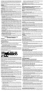
SELF-TIGHTENING CHUCK OPERATION (FIG. 6–8)
(DC925, DC926, DC935, DC936)
To insert a drill bit or other accessory:
1. Lock the trigger in the OFF position.
2. Grasp the chuck sleeve (F) with one hand and use the other hand to secure the tool as
shown in Figure 6. Rotate the sleeve counterclockwise (viewed from the front) far enough
to accept the desired bit or accessory.
3. Insert the bit or other accessory about 3/4” (19mm) into the chuck, as shown in Figure 7.
Grasp the chuck sleeve (E) securely and rotate the sleeve clockwise (viewed from the front)
with one hand while using the other hand to secure the tool. Rotate the sleeve clockwise
until sleeve cannot be rotated any further, as demonstrated in Figure 8. As the drill is being
operated in the forward position, the chuck will continually self tighten the jaws of the chuck
onto the bit or accessory to maximize the bit gripping strength.
To release the accessory, repeat Step 2.
OPERATION
Installing and Removing the Battery Pack (Fig. 9)
NOTE: Make sure your battery pack is fully charged.
To install the battery pack into the tool handle, align the notch inside the tool’s handle with the
battery pack and slide the battery pack firmly into the handle until you hear the lock snap into
place as shown in Figure 9.
To remove the battery pack from the tool, press the release buttons (G) and firmly pull the
battery pack out of the tool handle. Insert it into the charger as described in the charger section
of this manual.
Drill Operation
Turn the collar to the drill bit symbol. Install and tighten the desired drill bit in the chuck. Select
the desired speed/torque range using the gear shifter to match the speed and torque to the
planned operation. Follow these instructions for best results when drilling.
DRILLING
1. Turn the collar to the drill bit symbol for drilling or to the hammer symbol for hammerdrill-
ing.
2. Select the desired speed/torque range using the gear shifter to match the speed and torque
to the planned operation.
3. For WOOD, use twist bits, spade bits, power auger bits or hole saws. For METAL, use high-
speed steel twist drill bits or hole saws. Use a cutting lubricant when drilling metals. The
exceptions are cast iron and brass which should be drilled dry. For MASONRY, use carbide-
tipped bits or masonry bits. A smooth, even flow of dust indicates the proper drilling rate.
4. Always apply pressure in a straight line with the bit. Use enough pressure to keep the drill
bit biting, but do not push hard enough to stall the motor or deflect the bit.
5. Hold tool firmly with both hands to control the twisting action of the drill.
6. IF DRILL STALLS, it is usually because it is being overloaded. RELEASE TRIGGER
IMMEDIATELY, remove drill bit from work, and determine cause of stalling. DO NOT
CLICK TRIGGER OFF AND ON IN AN ATTEMPT TO START A STALLED DRILL – THIS
CAN DAMAGE THE DRILL.
7. Keep the motor running when pulling the bit back out of a drilled hole. This will help prevent
jamming.
Hammerdrill Operation
1. When drilling, use just enough force on the hammer to keep it from bouncing excessively
or “rising” off the bit. Too much force will cause slower drilling speeds, overheating, and a
lower drilling rate.
2. Drill straight, keeping the bit at a right angle to the work. Do not exert side pressure on the
bit when drilling as this will cause clogging of the bit flutes and a slower drilling speed.
3. When drilling deep holes, if the hammer speed starts to drop off, pull the bit partially out of
the hole with the tool still running to help clear debris from the hole.
4. For masonry, use carbide-tipped bits or masonry bits. A smooth even flow of dust indicates
the proper drilling rate.
Screwdriver Operation
Select the desired speed/torque range using the three-speed gear shift lever on the top of tool
to match the speed and torque to the planned operation. Insert the desired fastener accessory
into the chuck as you would any drill bit. Set the torque adjustment collar (Fig. 2) to the desired
setting. Make a few practice runs in scrap or unseen areas to determine the proper position of
the clutch collar.
MAINTENANCE
Cleaning
WARNING: Blow dirt and dust out of all air vents with dry air at least once a week. To mini-
mize the risk of eye injury, always wear ANSI Z87.1 approved eye protection when performing
this. Exterior plastic parts may be cleaned with a damp cloth and mild detergent. Although these
parts are highly solvent resistant, NEVER use solvents.
• Do not place any object on top of charger or place the charger on a soft surface that
might block the ventilation slots and result in excessive internal heat. Place the charger
in a position away from any heat source. The charger is ventilated through slots in the top
and the bottom of the housing.
• Do not operate charger with damaged cord or plug — have them replaced immediately.
• Do not operate charger if it has received a sharp blow, been dropped, or otherwise
damaged in any way. Take it to an authorized service center.
• Do not disassemble charger; take it to an authorized service center when service or
repair is required. Incorrect reassembly may result in a risk of electric shock, electrocution
or fire.
• Disconnect the charger from the outlet before attempting any cleaning. This will
reduce the risk of electric shock. Removing the battery pack will not reduce this risk.
• NEVER attempt to connect 2 chargers together.
• The charger is designed to operate on standard household electrical power
(120 Volts). Do not attempt to use it on any other voltage. This does not apply to the
vehicular charger.
SAVE THESE INSTRUCTIONS FOR FUTURE USE
Chargers
Your tool uses a 12.0, 14.4,18.0 Volt DEWALT Charger. Your battery can be charged in
D
EWALT 1 Hour Chargers, 15 Minute Chargers or Vehicular 12 volt charger. Be sure to read
all safety instructions before using your charger. Consult the chart at the end of this manual for
compatibility of chargers and battery packs.
Charging Procedure
DANGER: Electrocution hazard. 120 volts present at charging terminals. Do not probe with
conductive objects. Danger of electric shock or electrocution.
1. Plug the charger into an appropriate outlet before inserting battery pack.
2. Insert the battery pack into the charger. The red (charging) light will blink continuously indi-
cating that the charging process has started.
3. The completion of charge will be indicated by the red light remaining ON continuously. The
pack is fully charged and may be used at this time or left in the charger.
Using Automatic Tune-Up™ Mode
The automatic Tune-Up™ Mode equalizes or balances the individual cells in the battery pack
allowing it to function at peak capacity. Battery packs should be tuned up weekly or after
10 charge/discharge cycles or whenever the pack no longer delivers the same amount of
work. To use the Automatic Tune-Up™, place the battery pack in the charger and leave it for
at least 8 hours.
Indicator Light Operation
Charge Indicators
Some chargers are designed to detect certain problems that can arise with battery packs.
Problems are indicated by the red light flashing at a fast rate. If this occurs, re-insert battery
pack into the charger. If the problem persists, try a different battery pack to determine if the
charger is OK. If the new pack charges correctly, then the original pack is defective and should
be returned to a service center or other collection site for recycling. If the new battery pack
elicits the same trouble indication as the original, have the charger tested at an authorized
service center.
HOT/COLD PACK DELAY
Some chargers have a Hot/Cold Pack Delay feature: when the charger detects a battery that is
hot, it automatically starts a Hot Pack Delay, suspending charging until the battery has cooled.
After the battery has cooled, the charger automatically switches to the Pack Charging mode.
This feature ensures maximum battery life. The red light flashes long, then short while in the
Hot Pack Delay mode.
PROBLEM POWER LINE
Some chargers have a Problem Power Line indicator. When the charger is used with some por-
table power sources such as generators or sources that convert DC to AC, the charger may tem-
porarily suspend operation, flashing the red light with two fast blinks followed by a pause.
This indicates the power source is out of limits.
LEAVING THE BATTERY PACK IN THE CHARGER
The charger and battery pack can be left connected with the red light glowing indefinitely. The
charger will keep the battery pack fresh and fully charged.
NOTE: A battery pack will slowly lose its charge when kept out of the charger. If the battery pack
has not been kept on maintenance charge, it may need to be recharged before use. A battery
pack may also slowly lose its charge if left in a charger that is not plugged into an appropriate
AC source.
WEAK BATTERY PACKS: Chargers can also detect a weak battery. Such batteries are still
usable but should not be expected to perform as much work. In such cases, about 10 seconds
after battery insertion, the charger will beep rapidly 8 times to indicate a weak battery condition.
The charger will then go on to charge the battery to the highest capacity possible.
Important Charging Notes
1. Longest life and best performance can be obtained if the battery pack is charged when the
air temperature is between 65°F and 75°F (18°- 24°C). DO NOT charge the battery pack in
an air temperature below +40°F(+4.5°C), or above +105°F (+40.5°C). This is important and
will prevent serious damage to the battery pack.
2. The charger and battery pack may become warm to touch while charging. This is a normal
condition, and does not indicate a problem. To facilitate the cooling of the battery pack after
use, avoid placing the charger or battery pack in a warm environment such as in a metal
shed, or an uninsulated trailer.
3. If the battery pack does not charge properly:
a. Check current at receptacle by plugging in a lamp or other appliance
b. Check to see if receptacle is connected to a light switch which turns power off when you
turn out the lights.
c. Move charger and battery pack to a location where the surrounding air temperature is
approximately 65°F - 75°F (18°- 24°C).
d. If charging problems persist, take the tool, battery pack and charger to your local service
center.
4. The battery pack should be recharged when it fails to produce sufficient power on jobs which
were easily done previously. DO NOT CONTINUE to use under these conditions. Follow the
charging procedure. You may also charge a partially used pack whenever you desire with
no adverse affect on the battery pack.
5. Under certain conditions, with the charger plugged into the power supply, the exposed
charging contacts inside the charger can be shorted by foreign material. Foreign materials
of a conductive nature such as, but not limited to, steel wool, aluminum foil, or any buildup
of metallic particles should be kept away from charger cavities. Always unplug the charger
from the power supply when there is no battery pack in the cavity. Unplug charger before
attempting to clean.
6. Do not freeze or immerse charger in water or any other liquid.
WARNING: Shock hazard. Do not allow any liquid to get inside charger. Electric shock may
result.
CAUTION: Never attempt to open the battery pack for any reason. If the plastic housing of
the battery pack breaks or cracks, return to a service center for recycling.
KEY FEATURES AND FUNCTIONS
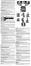
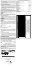
Variable Speed Switch (Fig. 1)
To turn the tool on, squeeze the trigger switch (A). To turn the tool off, release the trigger switch.
Your tool is equipped with a brake. The chuck will stop as soon as the trigger switch is fully
released.
NOTE: Continuous use in variable speed range is not recommended. It may damage the switch
and should be avoided.
Forward/Reverse Control Button (Fig. 1)
A forward/reverse control button (B) determines the direction the tool will spin and also serves
as a lock off button.
To select forward rotation, release the trigger switch and depress the for ward/re verse control
button on the right side of the tool.
To select reverse, depress the forward/reverse control button on the left side of the tool.
The center position of the control button locks the tool in the OFF position. When changing the
position of the control button, be sure the trigger is released.
NOTE: The first time the tool is run after changing the direction of rotation, you may hear a click
on start up. This is normal and does not indicate a problem.
Torque Adjustment Collar (Fig. 2)
Your tool has an adjustable torque screwdriver mechanism for driving and removing a wide
array of fastener shapes and sizes and in some models, a hammer mechanism for drilling into
masonry. Circling the collar (C) are numbers, a drill bit symbol, in some models, and a hammer
symbol. These numbers are used to set the clutch to deliver a torque range. The higher the
number on the collar, the higher the torque and the larger the fastener which can be driven. To
select any of the numbers, rotate until the desired number aligns with the arrow.
Three-Speed Gearing (Fig. 2)
The three-speed feature of your tool allows you to shift gears for greater versatility. To select
speed 1 (highest torque setting), turn the tool off and permit it to stop. Slide the gear shifter (D) all
the way to the left. Speed 2 (middle torque and speed setting) is in the middle position. Speed 3
(highest speed setting) is to the right.
NOTE: Do not change gears when the tool is running. Always allow the drill to come to a complete
stop before changing gears. If you have trouble changing gears, make sure that the gear shifter is
engaged in one of the three speed settings.
Side Handle
CAUTION: Always operate the tool with the side handle properly assembled. Hold tool
with both hands to maximize control.
Side handle clamps to the front of the gear case and may be rotated 360˚ to permit right- or
left-hand use. Side handle must be tightened sufficiently to resist the twisting action of the tool
if the accessory binds or stalls. Be sure to grip the side handle at the far end to control the tool
during a stall.
If model is not equipped with side handle, grip drill with one hand on the handle and one hand
on the battery pack.
NOTE: Side handle comes equipped on models DC920, DC925, DC926.
B
B
FIG. 1
A
A
FIG. 3
FIG. 2
C
D
FIG. 4
FIG. 5
FIG. 6
FIG. 7
FIG. 8
E
F
FIG. 9
G