


ENGLISH
41
Electrical Safety
The electric motor has been designed for one
voltage only. Always check that the battery pack
voltage corresponds to the voltage on the rating
plate. Also make sure that the voltage of your
charger corresponds to that of your mains.
Your DEWALT charger is double insulated
in accordance with EN 60335; therefore
no earth wire is required.
If the supply cord is damaged, it must be replaced
by a specially prepared cord available through the
DEWALT service organisation.
Mains Plug Replacement
(U.K. & Ireland Only)
If a new mains plug needs to be fitted:
• Safely dispose of the old plug.
• Connect the brown lead to the live terminal in
the plug.
• Connect the blue lead to the neutral terminal.
WARNING: No connection is to be
made to the earth terminal.
Follow the fitting instructions supplied with good
quality plugs. Recommended fuse: 3 A.
Using an Extension Cable
An extension cord should not be used unless
absolutely necessary. Use an approved extension
cable suitable for the power input of your charger
(see Technical Data). The minimum conductor size
is 1 mm
2
; the maximum length is 30 m.
When using a cable reel, always unwind the cable
completely.
ASSEMBLY AND ADJUSTMENTS
WARNING: Prior to assembly and
adjustment, always remove the battery
pack. Always switch off the tool before
inserting or removing the battery pack.
WARNING: Use only DEWALT battery
packs and chargers.
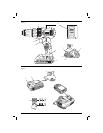
Inserting and Removing the
Battery Pack from the Tool (fi g. 2)
NOTE: For best results, make sure your battery
pack is fully charged.
TO INSTALL THE BATTERY PACK INTO THE TOOL HANDLE
1. Align the battery pack (j) with the rails inside the
tool’s handle (fig. 2).
2. Slide it into the handle until the battery pack is
firmly seated in the tool and ensure that it does
not disengage.
TO REMOVE THE BATTERY PACK FROM THE TOOL
1. Press the battery release button (k) and firmly
pull the battery pack out of the tool handle.
2. Insert battery pack into the charger as
described in the charger section of this manual.
FUEL GAUGE BATTERY PACKS (FIG. 2)
Some DEWALT battery packs include a fuel gauge
which consists of three green LED lights that
indicate the level of charge remaining in the battery
pack.
To actuate the fuel gauge, press and hold the fuel
gauge button (l). A combination of the three green
LED lights will illuminate designating the level of
charge left. When the level of charge in the battery
is below the usable limit, the fuel gauge will not
illuminate and the battery will need to be recharged.
NOTE: The fuel gauge is only an indication of the
charge left on the battery pack. It does not indicate
tool functionality and is subject to variation based
on product components, temperature and end-user
application.
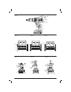
Variable Speed Trigger Switch (fi g. 1)
To turn the tool on, squeeze the trigger switch (a).
To turn the tool off, release the trigger switch. Your
tool is equipped with a brake. The chuck will stop as
soon as the trigger switch is fully released.
NOTE: Continuous use in variable speed range is
not recommended. It may damage the switch and
should be avoided.
Forward/Reverse Control Button
(fi g. 1)
A forward/reverse control button (b) determines the
direction of the tool and also serves as a lock-off
button.
To select forward rotation, release the trigger switch
and depress the forward/reverse control button on
the right side of the tool.
To select reverse, depress the forward/reverse
control button on the left side of the tool.
The center position of the control button locks
the tool in the off position. When changing the
position of the control button, be sure the trigger is
released.