


13
English
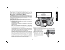
To remove the battery pack from the tool, press the battery
release buttons (P) and firmly pull the battery pack out of the tool
handle. Insert it into the charger as described in the charger manual.
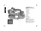
Removing and Installing Blades
WARNING: To reduce the risk of serious personal injury, turn
tool off and remove battery pack before making any adjustments
or removing/installing attachments or accessories. An accidental
start-up can cause injury.
CAUTION: Cut Hazard. Blade tension lever is under spring
pressure. Maintain control of lever when releasing blade tension.
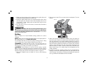
TO REMOVE BLADE (FIG. 2, 3)
1. Rotate the blade tension lever (H) clockwise until it stops to
release tension in blade.
2. Turn the saw over and place it on a workbench or table with the
motor to the left.
3. Begin removing the blade at the blade guard (L) and continue
around the pulleys (K). When removing the blade, tension may
be released and the blade may spring free. SAW BLADES ARE
SHARP. USE CARE IN HANDLING THEM.
4. Inspect the guide rollers (F1, F2) and remove any large chips which
may be lodged in them. Lodged chips can prevent rotation of the
guide rollers and cause flat spots on the guide rollers.
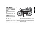
5. Rubber tires (M) are mounted on the pulleys (K). The rubber tires
should be inspected for looseness or damage when changing the
blade. Wipe any chips from the rubber tires on the pulleys. This will
extend tire life and keep the blade from slipping. If any looseness
or damage occurs, the tool should be brought to an authorized
D
EWALT service center for repair or replacement as soon as
possible. Continued use of the tool with loose or damaged rubber
tires will cause unstable travel of the band saw blade.
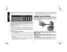
FIG. 5
BLADE DIRECTION
POSITION OF TEETH ON LEFT SIDE OF MACHINE
FIG 6
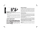
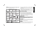
TO INSTALL BLADE (FIG. 2, 5–7)
1. Position the blade so that the teeth are on the bottom and angled
toward the work stop, as
FIG. 7
E
shown in Figures 2 and 5.
2. Slip the blade into the guide
rollers, as shown in Figure 6.
3. Holding the blade in the
guide rollers, place it around
both pulleys (K) and through
the work stop (E), as shown
in Figure 7.