


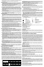
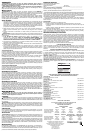
COMPONENTS (Fig. 1–4)
WARNING: Never modify the power tool or any part of it. Damage or personal injury could
result.
A. Trigger switch
B. Locking button
C. Reversing lever
D. Lock-out key
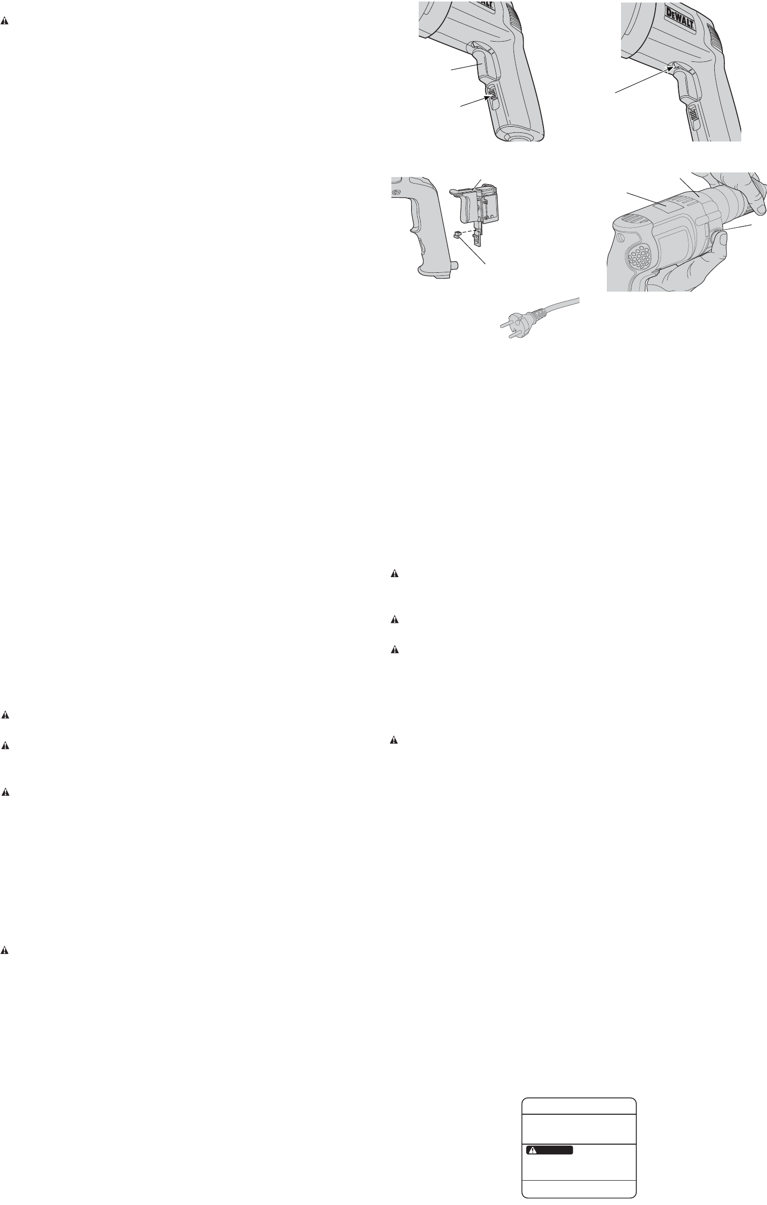
E. Indicator light (DW239, DW249)
F. Spindle lock button
INTENDED USE
These heavy-duty drills are designed for professional drilling applications. DO NOT use under
wet conditions or in presence of flammable liquids or gases.
These heavy-duty drills are professional power tools. DO NOT let children come into contact with
the tool. Supervision is required when inexperienced operators use this tool.
Anti-Lock Control (DW239, DW249)
Your DEWALT drill may come with an electronic feature called Anti-Lock Control. It is designed
to help you control the drill during a stall and keep it from pulling out of your hands. This may be
encountered when drilling in steel or using large bits in wood.
As a stall situation presents itself, the motor cycles on and off for a set period of time. This takes
up the reaction of the stall and allows you to keep the drill under control. The speed control
senses your release of the trigger and resets the motor to run again.
Figure 4 shows the instruction label (G) mounted behind the indicator light (E). There are three
alert modes.
1. Check Mode: Light will flash once each time the trigger is depressed to indicate everything
is functioning satisfactorily. Be sure to check for single flash periodically while using. If there
is no flash, the tool should be returned to a D
EWALT authorized service center for repair.
2. Engaged Mode: Should a stall condition still exist, the electronics will shut down the tool and
the light will be steady on. When the unit is running in normal mode, there will be no light.
3. Alert Mode: A series of continual flashes as the trigger is pulled indicates that the electron-
ics are no longer functioning. The tool may still be able to function without the benefit of
AntiLock Control but should be serviced as soon as possible.
Motor Brushes
DEWALT uses an advanced brush system which automatically stops the drill when the brushes
wear out. This prevents serious damage to the motor.
Switch (Fig. 1)
To start drill, depress trigger switch; to stop the drill, release trigger. To lock trigger in the on posi-
tion for continuous operation, depress trigger and push up locking button (B), then gently release
the trigger. To release the locking mechanism, depress the trigger fully, then release it. Before
using the tool each time, be sure that the locking button release mechanism is working freely.
Do not lock the switch on when drilling by hand so that you can instantly release the trigger
switch if the bit binds in the hole.
The locking button is for use only when the drill is mounted in a drill press stand or otherwise
held stationary.
Be sure to release the locking button before disconnecting the plug from the power supply.
Failure to do so will cause the tool to start immediately the next time it is plugged in. Damage
or injury could result.
VARIABLE SPEED TRIGGER SWITCH
This switch permits speed control: the farther the trigger is de pressed, the higher the speed of
the drill.
NOTE: Use lower speeds for starting holes without a center punch, drilling in metal or plastics,
driving screws or drilling ceramics. Higher speeds are better for drilling wood and composition
boards, and for using abrasive and polishing accessories.
REVERSING LEVER
The reversing lever changes the direction of rotation of the drill and is used when backing out
screws and jammed drill bits. To operate the tool in reverse, release the trigger switch and push
the lever to the left (when viewed from the chuck end) as shown in Figure 2. To operate the drill
in forward for drilling holes or driving screws (as well as when using other accessories) release
the trigger switch and push the lever to the right (when viewed from the chuck end).
Return the reversing lever to the forward position after all operations in reverse are completed.
SWITCH LOCK-ON
Your drill is equipped with a switch lock-on feature. If you wish to disable this feature, take your
tool to any authorized service center. The service center can provide a lock-out key (D) to prevent
the unit from being locked in the on position (Fig. 3).
OPERATION
WARNING: To reduce the risk of serious personal injury, turn tool off and disconnect tool
from power source before making any adjustments or removing/installing attachments
or accessories.
WARNING: To reduce the risk of personal injury, ALWAYS ensure workpiece is anchored
or clamped firmly. If drilling thin material, use a wood “back-up” block to prevent damage to the
material.
Side Handle
WARNING: To reduce the risk of personal injury, ALWAYS operate the tool with the side han-
dle properly installed and tightened. Failure to do so may result in the side handle slipping during
tool operation and subsequent loss of control. Hold tool with both hands to maximize control.
A side handle may be supplied with your drill. Side handles are included with these drills: DW231,
DW235-220, DW235G, DW236, DW237, DW238, DW239, DW245, DW246, DW248, DW249.
The side handle clamps to the front of the gear case and can be rotated 360 degrees to permit
right- or left-hand use.
Drilling
1. Use sharp drill bits only. For WOOD, use the low speed setting and twist drill bits, spade bits,
power auger bits, or hole saws. For METAL, use the low speed setting and steel twist drill bits
or hole saws. For MASONRY, such as brick, cement, cinder block, etc., use carbide-tipped
bits rated for percussion drilling. Use low speed for bits greater than 3/8" (10 mm).
2. Always apply pressure in a straight line with the bit. Use enough pressure to keep drill biting,
but do not push hard enough to stall the motor or deflect the bit.
3. Hold tool firmly with both hands to control the twisting action of the drill.
WARNING: Drill may stall if overloaded causing a sudden twist. Always expect the stall. Grip
the drill firmly with both hands to control the twisting action and avoid injury.
4. IF DRILL STALLS, it is usually because it is being overloaded or improperly used. RELEASE
TRIGGER IMMEDIATELY, remove drill bit from work, and determine cause of stalling. DO
NOT CLICK TRIGGER ON AND OFF IN AN ATTEMPT TO START A STALLED DRILL —
THIS CAN DAMAGE THE DRILL.
5. To minimize stalling or breaking through the material, reduce pressure on drill and ease the
bit through the last fractional part of the hole.
6. Keep the motor running when pulling the bit back out of a drilled hole. This will help prevent
jamming.
7. With variable speed drills there is no need to center punch the point to be drilled. Use a
slow speed to start the hole and accelerate by squeezing the trigger harder when the hole
is deep enough to drill without the bit skipping out.
DRILLING IN METAL
Start drilling with slow speed and increase to full power while applying firm pressure on the tool.
A smooth even flow of metal chips indicates the proper drilling rate. Use a cutting lubricant when
drilling metals. The exceptions are cast iron and brass which should be drilled dry.
NOTE: Large [5/16" (8 mm) to 1/2" (13 mm)] holes in steel can be made easier if a pilot hole
[5/32" (4 mm) to 3/16" (5 mm)] is drilled first.
DRILLING IN WOOD
Start drilling with slow speed and increase to full power while applying firm pressure on the tool.
Holes in wood can be made with the same twist drills used for metal. These bits may overheat
unless pulled out frequently to clear chips from the flutes. Work that is apt to splinter should be
backed up with a block of wood.
FIG. 1
B
FIG. 2
C
shown in forward position
illustré en marche avant
ilustrada en posición de
marcha hacia adelante
FIG. 3
220 VOLT PLUG
220 BOUCHON DE VOLT
220 TAPÓN DE VOLTIO
FIG. 4
DRILLING IN MASONRY
When drilling in masonry, use carbide-tipped bits rated for percussion drilling and be certain that
the bits are sharp. Use a constant and firm force on the tool to drill most effectively. A smooth,
even flow of dust indicates the proper drilling rate.
Keyed Chucks
Open chuck jaws by turning collar with fingers and insert shank of bit about 3/4" into chuck.
Tighten chuck collar by hand. Place chuck key in each of the three holes, and tighten in
CLOCKWISE direction. It’s important to tighten chuck with all three holes to prevent slippage.
To release bit, turn chuck key COUNTERCLOCKWISE in just one hole, then loosen the chuck
by hand. Any authorized D
EWALT service center can install a keyless chuck in place of a keyed
chuck.
Keyless Chucks
Open chuck jaws by turning plastic collar with fingers and insert shank of bit about 3/4" into
chuck. Tighten plastic collar CLOCKWISE while depressing spindle lock button (F) on the right
side of the tool housing (Fig. 4). To release bit, turn plastic collar COUN TERCLOCKWISE while
depressing the spindle lock button (Fig. 4).
NOTE: DO NOT DEPRESS LOCK BUTTON WHILE OPERATING DRILL or while the chuck is
moving.
MAINTENANCE
WARNING: To reduce the risk of serious personal injury, turn tool off and disconnect tool
from power source before making any adjustments or removing/installing attachments
or accessories.
Cleaning
WARNING: Blow dirt and dust out of all air vents with dry air at least once a week. Wear
proper ANSI Z87.1 (CAN/CSA Z94.3) eye protection and proper NIOSH/OSHA/MSHA
respiratory protection when performing this.
WARNING: Never use solvents or other harsh chemicals for cleaning the non-metallic parts
of the tool. These chemicals may weaken the plastic materials used in these parts. Use a cloth
dampened only with water and mild soap. Never let any liquid get inside the tool; never immerse
any part of the tool into a liquid.
Lubrication
Self-lubricating bearings are used in the tool and periodic relubrication is not required. In the
unlikely event that service is ever needed, take your tool to an authorized service location.
Accessories
WARNING: Since accessories, other than those offered by DEWALT, have not been tested
with this product, use of such accessories with this tool could be hazardous. To reduce the risk
of injury, only D
EWALT, recommended accessories should be used with this product.
Recommended accessories for use with your tool are available at extra cost from your local dealer
or authorized service center. If you need assistance in locating any accessory, please contact
D
EWALT Industrial Tool Co., 701 East Joppa Road, Baltimore, MD 21286, call 1-800-4-DEWALT
(1-800-433-9258) or visit our website www.dewalt.com.
Repairs
To assure product SAFETY and RELIABILITY, repairs, maintenance and adjustments (including
brush inspection and replacement) should be performed by a DEWALT factory service center,
a D
EWALT authorized service center or other qualified service personnel. Always use identical
replacement parts.
Three Year Limited Warranty
DEWALT will repair, without charge, any defects due to faulty materials or workmanship for
three years from the date of purchase. This warranty does not cover part failure due to normal
wear or tool abuse. For further detail of warranty coverage and warranty repair information, visit
www.dewalt.com or call 1-800-4-D
EWALT (1-800-433-9258). This warranty does not apply to
accessories or damage caused where repairs have been made or attempted by others. This
warranty gives you specific legal rights and you may have other rights which vary in certain
states or provinces.
In addition to the warranty, D
EWALT tools are covered by our:
1 YEAR FREE SERVICE
D
EWALT will maintain the tool and replace worn parts caused by normal use, for free, any time
during the first year after purchase.
90 DAY MONEY BACK GUARANTEE
If you are not completely satisfied with the performance of your D
EWALT Power Tool, Laser, or
Nailer for any reason, you can return it within 90 days from the date of purchase with a receipt
for a full refund – no questions asked.
LATIN AMERICA: This warranty does not apply to products sold in Latin America. For products
sold in Latin America, see country specific warranty information contained either in the
packaging, call the local company or see website for warranty information.
FREE WARNING LABEL REPLACEMENT: If your warning labels become illegible or are
missing, call 1-800-4-D
EWALT for a free replacement.
DWXXX
1/4" (6mm)
VSR DRILL
AVERTISSEMENT
TO REDUCE THE RISK OF INJURY, USER MUST READ AND
UNDERSTAND INSTRUCTION MANUAL. WHEN SERVICING,
USE ONLY IDENTICAL REPLACEMENT PARTS. ALWAYS
WEAR EYE PROTECTION. À TITRE PRÉVENTIF, LIRE LE
GUIDE D'UTILISATION.
SER.
PATENTS PENDING
D
EWALT INDUSTRIAL TOOL CO., BALTIMORE, MD 21286 U.S.A.
FOR SERVICE INFORMATION, CALL 1-800-4-D
E
WALT www.D
E
WALT.com
WARNING
A
G
E
(DW239, DW249)
F
SWITCH ASSEMBLY
INTERRUPTEUR
MONTAJE DEL INTERRUPTOR
D