


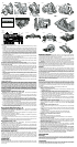
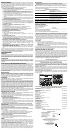

TO INSTALL THE BLADE (FIG. 1–4)
1. Place inner clamp washer (G) on saw spindle with the large flat surface facing out toward
the blade.
2. Retract the lower blade guard (F) and place blade on saw spindle against the inner clamp
washer, making sure that the blade will rotate in the proper direction (the direction of the
rotation arrow on the saw blade and the teeth must point in the same direction as the direc-
tion of rotation arrow on the saw). Do not assume that the printing on the blade will always
be facing you when properly installed. When retracting the lower blade guard to install the
blade, check the condition and operation of the lower blade guard to assure that it is work-
ing properly. Make sure it moves freely and does not touch the blade or any other part, in
all angles and depths of cut.
3. Place outer clamp washer (H) on saw spindle with the large flat surface against the blade
and the wording on the outer clamp washer facing you.
4. Thread blade clamping screw (E) into saw spindle by hand (screw has right-hand threads
and must be turned clockwise to tighten).
5. Depress the blade lock (I) while turning the saw spindle with the blade wrench until the
blade lock engages and the blade stops rotating.
6. Tighten the blade clamping screw firmly with the blade wrench.
NOTE: Never engage the blade lock while saw is running, or engage in an effort to stop the tool.
Never turn the saw on while the blade lock is engaged. Serious damage to your saw will result.
TO REPLACE THE BLADE
1. To loosen the blade clamping screw (E), depress the blade lock (I) and turn the saw spin-
dle with the blade wrench until the blade lock engages and the blade stops rotating. With
the blade lock engaged, turn the blade clamping screw clockwise with the blade wrench
(screw has right-hand threads and must be turned counterclockwise to loosen).
2. Remove the blade clamping screw (E) and outer clamp washer (H) only. Remove old
blade.
3. Clean any sawdust that may have accumulated in the guard or clamp washer area and
check the condition and operation of the lower blade guard as previously outlined. Do not
lubricate this area.
4. Select the proper blade for the application (see Blades). Always use blades that are the
correct size (diameter) with the proper size and shape center hole for mounting on the saw
spindle. Always assure that the maximum recommended speed (rpm) on the saw blade
meets or exceeds the speed (rpm) of the saw.
5. Follow steps 2 through 6 under To Install the Blade, making sure that the blade will rotate
in the proper direction.
LOWER BLADE GUARD
WARNING: The lower blade guard is a safety feature which reduces the risk of serious
personal injury. Never use the saw if the lower guard is missing, damaged, misassem-
bled or not working properly. Do not rely on the lower blade guard to protect you under
all circumstances. Your safety depends on following all warnings and precautions as
well as proper operation of the saw. Check lower guard for proper closing before each
use as outlined in Additional Safety Rules for Circular Saws. If the lower blade guard is
missing or not working properly, have the saw serviced before using. To assure prod-
uct safety and reliability, repair, maintenance and adjustment should be performed by
an authorized service center or other qualified service organization, always using iden-
tical replacement parts.
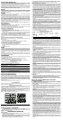
Cutting Depth Adjustment (Fig. 5, 6)
CAUTION: ALWAYS TURN OFF AND DISCONNECT TOOL BEFORE CHANGING
ACCESSORIES OR MAKING ANY ADJUSTMENTS.
1. Hold the saw firmly. Raise the depth adjustment lever (J) to loosen and move shoe to
obtain the desired depth of cut, as shown. Make sure the depth adjustment lever has been
retightened (lowered) before operating the saw.
2. Your saw is equipped with a carbide tipped saw blade for long life and efficient cutting.
3. Setting the saw at the proper cutting depth keeps blade friction to a minimum, removes
sawdust from between the blade teeth, results in cooler, faster sawing and reduces the
chance of kickback. Align the appropriate mark on the depth adjustment strap with triangle
on the upper blade guard (K). Your depth is set.
4. For the most efficient cutting action using a carbide tipped saw blade, set the depth adjust-
ment so that about one half of a tooth projects below the surface of the wood to be cut.
5. A method of checking for the correct cutting depth is shown in Figure 6. Lay a piece of the
material you plan to cut along the side of the blade, as shown in the figure, and observe
how much tooth projects beyond the material.
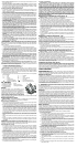
Bevel Angle Adjustment (Fig. 7, 8)
CAUTION: ALWAYS TURN OFF AND DISCONNECT TOOL BEFORE CHANGING
ACCESSORIES OR MAKING ANY ADJUSTMENTS.
The full range of bevel adjustment on the DW367 is 0 to 50 degrees. The pivot bracket is
graduated in 5 degree increments.
On the DW368 and DW369, the full range of bevel adjustment is 0 to 56 degrees. The pivot
bracket is graduated in increments of 1 degree.
There is a bevel angle adjustment mechanism (M) consisting of a quadrant with a pointer (N)
and a lever (L) on the front of the saw.
1. To set the saw for a bevel cut, raise the lever (L) or turn the knob (O) to loosen the bevel
adjustment.
2. Tilt the shoe to the desired angle by aligning the pointer with the desired angle mark on the
pivot bracket.
3. Retighten the bevel adjustment by lowering the lever or turning the knob.
Bevel Detent (Fig. 7, 8)
CAUTION: ALWAYS TURN OFF AND DISCONNECT TOOL BEFORE CHANGING
ACCESSORIES OR MAKING ANY ADJUSTMENTS.
The DW367 has a bevel stop at 45 degrees. To set the bevel at an angle greater than
45 degrees, tilt the shoe to 45 degrees, then slide the knob and bolt into the upper slot. When
you reach the desired angle, tighten the knob.
The DW368 and DW369 are equipped with a bevel detent feature. As you tilt the shoe you will
hear a click and feel the shoe stop at both 22.5 and 45 degrees. If either of these is the desired
angle, retighten the lever (L) by lowering it. If you desire another angle, continue tilting the shoe
until the pointer aligns with the desired mark.
Kerf Indicator (Figure 9)
The front of the saw shoe has a kerf indicator for vertical and bevel cutting. This indicator
enables you to guide the saw along cutting lines penciled on the material being cut. The
indicator lines up with the left (inner) side of the saw blade, which makes the slot or "kerf" cut
by the moving blade fall to the right of the indicator. The ribs on the front of the DW368
and DW369 shoe are at 1/4" (6.35 mm) spacing. The notches on the front of the shoe are at
1/2" (13 mm) intervals.
OPERATION
Switch (Fig. 1)
Pull the trigger switch (B) to turn the motor on. Releasing the trigger turns the motor off. This
tool has no provision to lock the switch in the on position, and the tool should never be locked
on in any way.
Workpiece Support
Figure 10 and 12 show proper sawing position. Figure 11 and 13 show an unsafe condition.
Hands should be kept away from cutting area, and power cord is positioned clear of the cut-
ting area so that it will not get caught or hung up on the work.
To avoid kickback, DO support board or panel NEAR the cut, (Fig. 10 and 12). DON’T support
board or panel away from the cut (Fig. 11 and 13). When operating the saw, keep the cord
away from the cutting area and prevent it from becoming hung up on the work piece.
WARNING: It is important to support the work properly and to hold the saw firmly to pre-
vent loss of control which could cause personal injury; Figure 12 illustrates typical hand sup-
port of the saw.
ALWAYS DISCONNECT SAW BEFORE MAKING ANY ADJUSTMENTS! Place the work with
its “good” side - the one on which appearance is most important - down. The saw cuts upward,
so any splintering will be on the work face that is up when you saw it.
Cutting
Support the work so that the waste will be on your right. Place the wider portion of the saw
shoe on that part of the work piece which is solidly supported, not on the section that will fall
off when the cut is made. As examples, Figure 12 illustrates the RIGHT way to cut off the end
of a board, and Figure 13 the WRONG way. Always clamp work. Don’t try to hold short pieces
by hand! Remember to support cantilevered and overhanging material. Use caution when
sawing material from below.
Be sure that the saw is up to full speed before blade contacts material to be cut. Starting the
saw with blade against material to be cut or pushed forward into kerf can result in kickback.
Push the saw forward at a speed which allows the blade to cut without laboring. Hardness and
toughness can vary even in the same piece of material, and knotty or damp sections can put
a heavy load on the saw. When this happens, push the saw more slowly, but hard enough to
keep it working without much decrease in speed.
Kickback
When the saw blade becomes pinched or twisted in the cut, kickback can occur. The saw is
thrust rapidly back toward the operator. When the blade is pinched or bound tightly by the kerf
closing down, the blade stalls and the motor reaction drives the unit backward. When the blade
becomes twisted or misaligned in the cut, the teeth at the back edge of the blade can dig into
the top surface of the wood causing the blade to climb out of the kerf and jump back toward
the operator.
Kickback is more likely to occur when any of the following conditions exist.
1. IMPROPER WORKPIECE SUPPORT
A. Sagging or improper lifting of the cut off piece can cause pinching of the blade and lead
to kickback. (Figure 11)
B. Cutting through material supported at the outer ends only can cause kickback. As the
material weakens it sags, closing down the kerf and pinching the blade.
C. Cutting off a cantilevered or overhanging piece of material from the bottom up in a
vertical direction can cause kickback. The falling cut off piece can pinch the blade.
D. Cutting off long narrow strips (as in ripping) can cause kickback. The cut off strip can
sag or twist closing the kerf and pinching the blade.
E. Snagging the lower guard on a surface below the material being cut momentarily
reduces operator control. The saw can lift partially out of the cut increasing the chance
of blade twist.
2. IMPROPER DEPTH OF CUT SETTING ON SAW
To make the most efficient cut, the blade should protrude only far enough to expose
1/2 of a tooth as shown in figure 5. This allows the shoe to support the blade and
minimizes twisting and pinching in the material. See the section titled Cutting Depth
Adjustment.
3. BLADE TWISTING (MISALIGNMENT IN CUT)
A. Pushing harder to cut through a knot, a nail, or a hard grain area can cause the blade
to twist.
B. Trying to turn the saw in the cut (trying to get back on the marked line) can cause blade
twist.
C. Over-reaching or operating the saw with poor body control (out of balance), can result
in twisting the blade.
D. Changing hand grip or body position while cutting can result in blade twist.
E. Backing up the saw to clear blade can lead to twist if it is not done carefully.
4. MATERIALS THAT REQUIRE EXTRA ATTENTION
A. Wet lumber
B. Green lumber (material freshly cut or not kiln dried)
C.Pressure treated lumber (material treated with preservatives or anti-rot chemicals)
5. USE OF DULL OR DIRTY BLADES
Dull blades cause increased loading of the saw. To compensate, an operator will usually
push harder which further loads the unit and promotes twisting of the blade in the kerf.
Worn blades may also have insufficient body clearance which increases the chance of
binding and increased loading.
6. LIFTING THE SAW WHEN MAKING BEVEL CUTS
Bevel cuts require special operator attention to proper cutting techniques – especially
guidance of the saw. Both blade angle to the shoe and greater blade surface in the mate-
rial increase the chance for binding and misalignment (twist) to occur.
7. RESTARTING A CUT WITH THE BLADE TEETH JAMMED AGAINST THE MATERIAL
The saw should be brought up to full operating speed before starting a cut or restarting a
cut after the unit has been stopped with the blade in the kerf. Failure to do so can cause
stalling and kickback.
Any other conditions which could result in pinching, binding, twisting, or misalignment of the
blade could cause kickback. Refer to Additional Safety Instructions and Operation for
procedures and techniques that will minimize the occurrence of kickback.
MAINTENANCE
Cleaning
Use only mild soap and a damp cloth to clean the tool. Many household cleaners contain
chemicals which could seriously damage plastic. Do not use gasoline, turpentine, lacquer or
paint thinner, dry cleaning fluids or similar products. Never let any liquid get inside the tool;
never immerse any part of the tool in a liquid.
Lubrication
Self lubricating ball and roller bearings are used in the tool and relubrication is not required.
However, it is recommended that, once a year, you take or send the tool to a service center
for a thorough cleaning, inspection and lubrication of the gear case.
FIG. 1
FIG. 2
FIG. 3
FIG. 5
FIG. 6
FIG. 4
J
LOOSEN
TIGHTEN
DW369
J
K
DW367, DW368
DW367
FIG. 11
FIG. 12
FIG. 13
FIG. 10
I
FIG. 14
G
E
H
FIG. 8
FIG. 9
0˚
45˚
1/4”
6.35 mm
1/2”
13 mm
FIG. 7
L
M
O
TIGHTEN
LOOSEN
N